


2-1
2. Unit Description
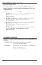
2.1. RPS820 and RPS830 Front Panel
The front panels of both RPS820 and RPS830 models include two LED
indicators which function as follows:
• Power: Lights when power is applied to the unit. Note that this
indicator does not show the On/Off status of the switched outlets.
• System Ready: Flashes when the unit is ready to receive commands.
BUS A BUS B
A-1 A-2 A-3 A-4 B-5 B-6 B-7 B-8
MAIN POWER
COM
10BaseT
ACT
RDY
ON
DEF
A
B
1
2
3
4
5
6
7
8
9
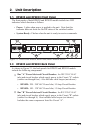
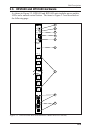
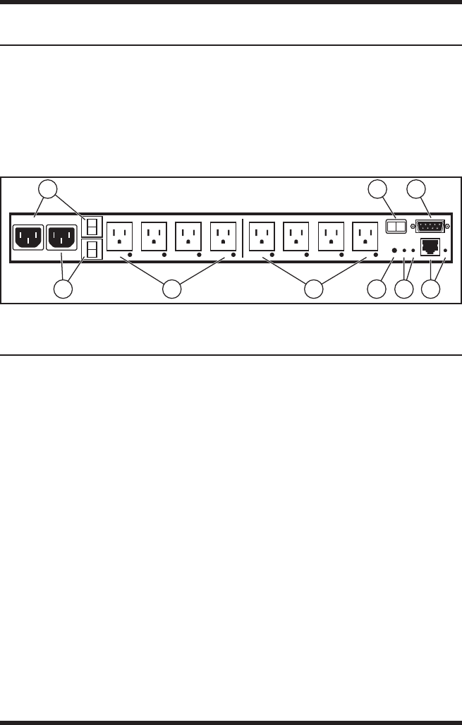
Figure 2.1: RPS820 and RPS830; Back Panel (Model RPS830 Shown)
2.2. RPS820 and RPS830 Back Panel
As shown in Figure 2.1, the back panels for RPS820 and RPS830 models
include the following components:
➀
Bus "A" Power Inlet and Circuit Breaker: An IEC-320-C14 AC
inlet and circuit breaker which supply power to the Circuit "A" outlets
(outlets one through four.) Also includes cable keeper (not shown.)
• RPS820: 208 - 240 VAC Power Inlet, 10 Amp Circuit Breaker.
• RPS830: 100 - 120 VAC Power Inlet, 15 Amp Circuit Breaker.
➁
Bus "B" Power Inlet and Circuit Breaker: An IEC-320-C14 AC
inlet and circuit breaker which supply power to the Circuit "B" outlets
(outlets five through 8.) Also includes cable keeper (not shown.)
Includes the same components listed for Circuit "A".