


Philips Semiconductors
ISP1122
USB stand-alone hub
Product specification Rev. 03 — 29 March 2000 11 of 48
9397 750 07002
© Philips Electronics N.V. 2000. All rights reserved.
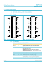
8. Endpoint descriptions
Each USB device is logically composed of several independent endpoints. An
endpoint acts as a terminus of a communication flow between the host and the
device. At design time each endpoint is assigned a unique number (endpoint
identifier, see Tabl e 5). The combination of the device address (given by the host
during enumeration), the endpoint number and the transfer direction allows each
endpoint to be uniquely referenced.
The ISP1122 has two endpoints, endpoint 0 (control) and endpoint 1 (interrupt).
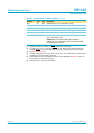
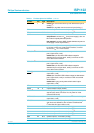
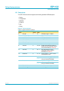
[1] IN: input for the USB host; OUT: output from the USB host.
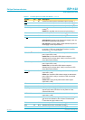
8.1 Hub endpoint 0 (control)
All USB devices and functions must implement a default control endpoint (ID = 0).
This endpoint is used by the host to configure the device and to perform generic USB
status and control access.
The ISP1122 hub supports the following USB descriptor information through its
control endpoint 0, which can handle transfers of 64 bytes maximum:
•
Device descriptor
•
Configuration descriptor
•
Interface descriptor
•
Endpoint descriptor
•
Hub descriptor
•
String descriptor.
8.2 Hub endpoint 1 (interrupt)
Endpoint 1 is used by the ISP1122 hub to provide status change information to the
host. This endpoint can be accessed only after the hub has been configured by the
host (by sending the Set Configuration command).
Endpoint 1 is an interrupt endpoint: the host polls it once every 255 ms by sending an
IN token. If the hub has detected no change in the port status it returns a NAK (Not
AcKnowledge) response to this request, otherwise it sends the Status Change byte
(see Table 6).
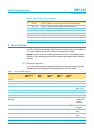
Table 5: Hub endpoints
Function Ports Endpoint
identifier
Transfer
type
Direction
[1]
Max. packet
size (bytes)
Hub
0: upstream
1 to 5: downstream
0 control
OUT 64
IN 64
1 interrupt IN 1