


Philips Semiconductors
ISP1122
USB stand-alone hub
Product specification Rev. 03 — 29 March 2000 33 of 48
9397 750 07002
© Philips Electronics N.V. 2000. All rights reserved.
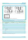
[1] Operating modes 0, 1, 4 and 5; see Table 4.
[1] Test circuit: see Figure 22.
[2] Excluding the first transition from Idle state.
[3] Characterized only, not tested. Limits guaranteed by design.
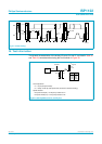
Table 31: Dynamic characteristics: overcurrent sense pins
V
CC
= 4.0 to 5.5 V; V
GND
=0V; T
amb
=
−
40 to
+
85
°
C; unless otherwise specified.
Symbol Parameter Conditions Min Typ Max Unit
t
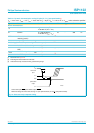
trip
overcurrent trip response time
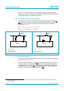
from
OCn LOW to PSWn HIGH
see Figure 14
[1]
--15ms
Table 32: Dynamic characteristics: analog I/O pins (D+, D−); full-speed mode
[1]
V
CC
= 4.0 to 5.5 V; V
GND
=0V;T
amb
=
−
40 to
+
85
°
C; C
L
= 50 pF; R
PU
= 1.5 k
Ω
on D
+
to V
TERM
.; unless otherwise specified.
Symbol Parameter Conditions Min Typ Max Unit
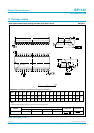
Driver characteristics
t
FR
rise time C
L
=50pF;
10 to 90% of |V
OH
− V
OL
|
4 - 20 ns
t
FF
fall time C
L
=50pF;
10 to 90% of |V
OH
− V
OL
|
4 - 20 ns
FRFM differential rise/fall time
matching (t
FR
/t
FF
)
[2]
90 - 111.11 %
V
CRS
output signal crossover voltage
[2] [3]
1.3 - 2.0 V
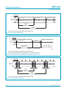
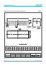
Data source timing
t
DJ1
source differential jitter for
consecutive transitions
see Figure 15
[2] [3]
−3.5 - +3.5 ns
t
DJ2
source differential jitter for
paired transitions
see Figure 15
[2] [3]
−4- +4ns
t
FEOPT
source EOP width see Figure 16
[3]
160 - 175 ns
t
FDEOP
source differential data-to-EOP
transition skew
see Figure 16
[3]
−2- +5ns
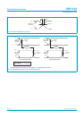
Receiver timing
t
JR1
receiver data jitter tolerance for
consecutive transitions
see Figure 17
[3]
−18.5 - +18.5 ns
t
JR2
receiver data jitter tolerance for
paired transitions
see Figure 17
[3]
−9- +9ns
t
FEOPR
receiver SE0 width accepted as EOP;
see Figure 16
[3]
82--ns
t
FST
width of SE0 during differential
transition
rejected as EOP;
see Figure 18
[3]
--14ns
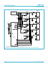
Hub timing (downstream ports configured as full-speed)
t
FHDD
hub differential data delay
(without cable)
see Figure 19;
C
L
=0pF
[3]
--44ns
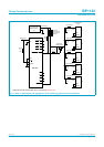
t
FSOP
data bit width distortion after
SOP
see Figure 19
[3]
−5- +5ns
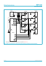
t
FEOPD
hub EOP delay relative to t
HDD
see Figure 20
[3]
0 - 15 ns
t
FHESK
hub EOP output width skew see Figure 20
[3]
−15 - +15 ns