


Philips Semiconductors
ISP1122
USB stand-alone hub
Product specification Rev. 03 — 29 March 2000 7 of 48
9397 750 07002
© Philips Electronics N.V. 2000. All rights reserved.
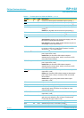
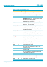
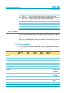
OC5/GOC
[3]
7 AI/I modes 5, 7: overcurrent sense input for downstream port 5
(analog
[5]
)
modes 0, 1, 3: global overcurrent sense input (analog
[5]
)
DM4 8 AI/O downstream port 4 D− connection (analog)
[4]
DP4 9 AI/O downstream port 4 D+ connection (analog)
[4]
SP/BP 10 I selects power mode:
self-powered: connect to V
DD
(local power supply); also use
this mode for hybrid-powered operation
bus-powered: connect to GND; disable downstream port 5 to
meet supply current requirements
[4]
HUBGL 11 O hub GoodLink LED indicator output (open-drain, 6 mA);
to connect an LED use a 330 Ω series resistor; if unused
connect to V
CC
via a 10 kΩ resistor
PSW3/GL3
[3]
12 O modes 4 to 6: power switch control output for downstream
port 3 (open-drain, 6 mA)
modes 0 to 3, 7: GoodLink LED indicator output for
downstream port 3 (open-drain, 6 mA); to connect an LED
use a 330 Ω series resistor
PSW4/GL4
[3]
13 O modes 4 to 6: power switch control output for downstream
port 4 (open-drain, 6 mA)
modes 0 to 3, 7: GoodLink LED indicator output for
downstream port 4 (open-drain, 6 mA); to connect an LED
use a 330 Ω series resistor
PSW5/GL5/
GPSW
[3]
14 O mode 5: power switch control output for downstream port 5
(open-drain, 6 mA)
modes 3, 7: GoodLink LED indicator output for downstream
port 5 (open-drain, 6 mA); to connect an LED use a 330 Ω
series resistor
modes 0 to 2: gang mode power switch control output
(open-drain, 6 mA)
XTAL1 15 I crystal oscillator input (6 MHz)
XTAL2 16 O crystal oscillator output (6 MHz)
RESET
[2]
17 I reset input (Schmitt trigger); a LOW level produces an
asynchronous reset; connect to V
CC
for power-on reset
(internal POR circuit)
OPTION/SCL 18 I/O mode selection input; also functions as I
2
C-bus clock output
(open-drain, 6 mA)
INDV/SDA 19 I/O selects individual (HIGH) or global (LOW) power switching
and overcurrent detection; also functions as bidirectional
I
2
C-bus data line (open-drain, 6 mA)
DM5 20 AI/O downstream port 5 D− connection (analog)
[4]
DP5 21 AI/O downstream port 5 D+ connection (analog)
[4]
DM1 22 AI/O downstream port 1 D− connection (analog)
[6]
DP1 23 AI/O downstream port 1 D+ connection (analog)
[6]
DM0 24 AI/O upstream port D− connection (analog)
DP0 25 AI/O upstream port D+ connection (analog)
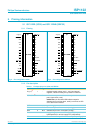
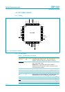
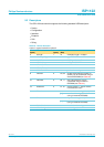
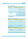
Table 3: Pin description for LQFP32
…continued
Symbol
[1]
Pin Type Description