


Philips Semiconductors
ISP1122
USB stand-alone hub
Product specification Rev. 03 — 29 March 2000 24 of 48
9397 750 07002
© Philips Electronics N.V. 2000. All rights reserved.
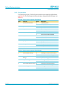
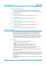
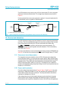
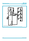
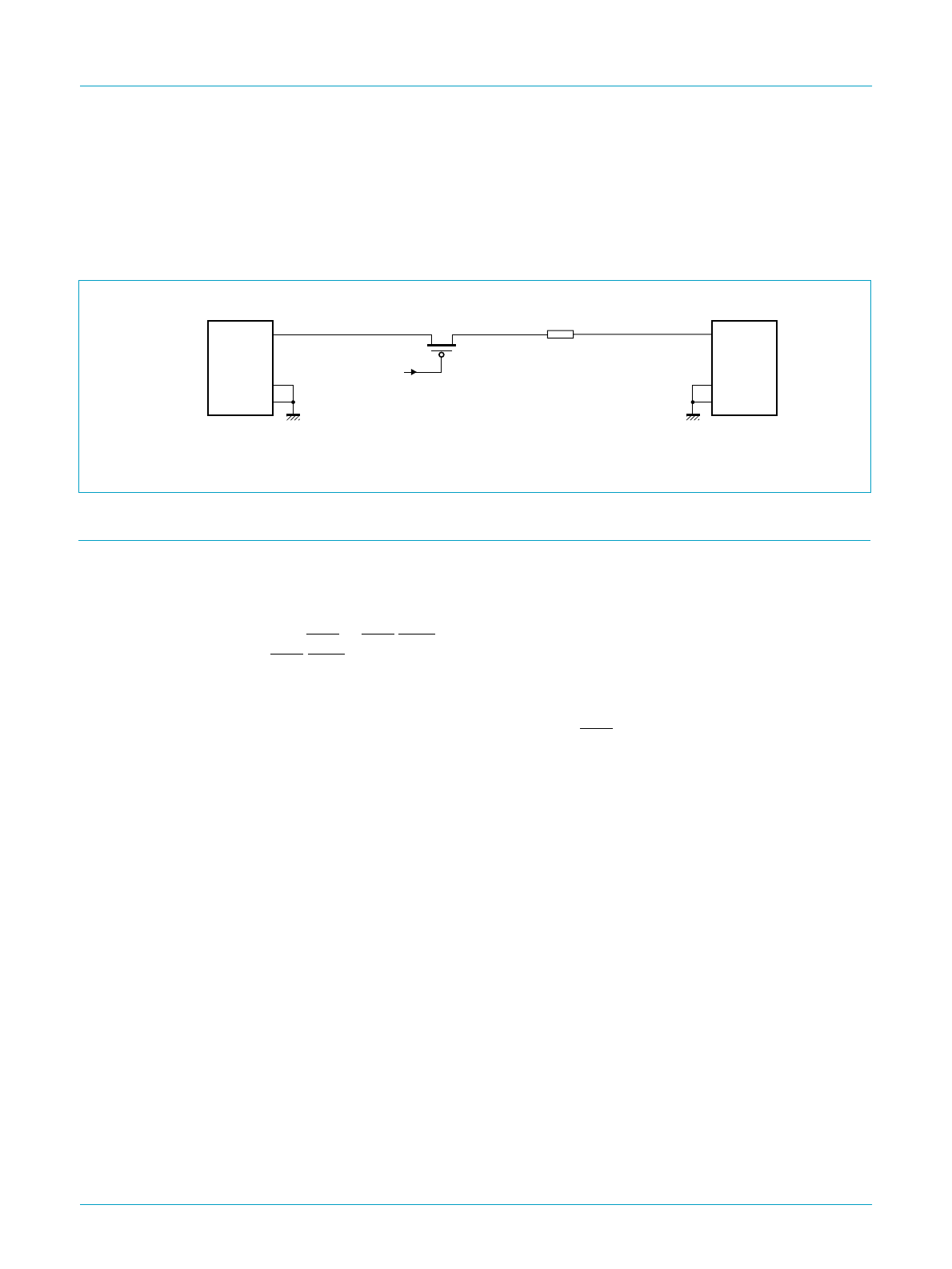
The PCB resistance may cause a drop of 25 mV, which leaves 75 mV for the power
switch and overcurrent sense device. The voltage drop components are shown in
Figure 8.
For bus-powered hubs overcurrent protection is optional. It may be implemented for
all downstream ports on a global or individual basis.
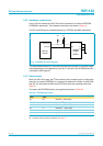
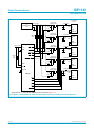
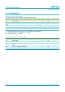
12. Overcurrent detection
The ISP1122 has an analog overcurrent detection circuit for monitoring downstream
port lines. This circuit automatically reports an overcurrent condition to the host and
turns off the power to the faulty port. The host must reset the condition flag.
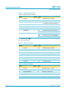
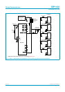
Pins OC1 to OC5/GOC are used for individual port overcurrent detection. Pin
OC5/GOC can also be used for global overcurrent detection. This is controlled by
input INDV (see Tabl e 4).
The overcurrent detection circuit can be switched off using an external EEPROM (see
Table 23). In this case, the overcurrent pins OCn function as logic inputs (TTL level).
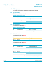
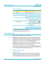
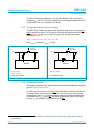
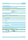
12.1 Overcurrent circuit description
The integrated overcurrent detection circuit of ISP1122 senses the voltage drop
across the power switch or an extra low-ohmic sense resistor. When the port draws
too much current, the voltage drop across the power switch exceeds the trip voltage
threshold (∆V
trip
). The overcurrent circuit detects this and switches off the power
switch control signal after a delay of 15 ms (t
trip
). This delay acts as a ‘debounce’
period to minimize false tripping, especially during the inrush current produced by ‘hot
plugging’ of a USB device.
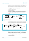
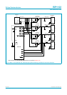
12.2 Power switch selection
From the voltage drop analysis given in Figure 6, Figure 7 and Figure 8, the power
switch has a voltage drop budget of 75 mV. For individual self-powered mode, the
current drawn per port can be up to 500 mA. Thus the power switch should have
maximum on-resistance of 150 mΩ.
If the voltage drop due to the hub board resistance can be minimized, the power
switch can have more voltage drop budget and therefore a higher on-resistance.
Power switches with a typical on-resistance of around 100 mΩ fit into this application.
(1) Includes PCB traces, ferrite beads, etc.
Fig 8. Typical voltage drop components in bus-powered mode (no overcurrent detection).
handbook, full pagewidth
MGR783
low-ohmic
PMOS switch
ISP1122
power
switch
V
BUS
D+
D−
GND
SHIELD
V
BUS
D+
D−
GND
SHIELD
4.40 V(min)4.50 V(min)
downstream
port
connector
upstream
port
connector
hub board
resistance
voltage drop
25 mV
voltage drop
75 mV
(1)