


Philips Semiconductors
ISP1122
USB stand-alone hub
Product specification Rev. 03 — 29 March 2000 34 of 48
9397 750 07002
© Philips Electronics N.V. 2000. All rights reserved.
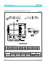
[1] Test circuit: see Figure 22.
[2] Excluding the first transition from Idle state.
[3] Characterized only, not tested. Limits guaranteed by design.
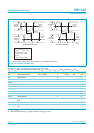
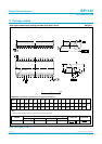
Table 33: Dynamic characteristics: analog I/O pins (D+, D−); low-speed mode
[1]
V
CC
= 4.0 to 5.5 V; V
GND
=0V;T
amb
=
−
40 to
+
85
°
C; C
L
= 50 pF; R
PU
= 1.5 k
Ω
on D
−
to V
TERM
; unless otherwise specified.
Symbol Parameter Conditions Min Typ Max Unit
Driver characteristics
t
LR
rise time C
L
= 200 to 600 pF;
10 to 90% of |V
OH
− V
OL
|
75 - 300 ns
t
LF
fall time C
L
= 200 to 600 pF;
10 to 90% of |V
OH
− V
OL
|
75 - 300 ns
LRFM differential rise/fall time
matching (t
LR
/t
LF
)
[2]
80 - 125 %
V
CRS
output signal crossover voltage
[2] [3]
1.3 - 2.0 V
Hub timing (downstream ports configured as low-speed)
t
LHDD
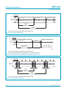
hub differential data delay see Figure 19 - - 300 ns
t
LSOP
data bit width distortion after
SOP
see Figure 19
[3]
−60 - +60 ns
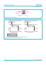
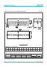
t
LEOPD
hub EOP delay relative to t
HDD
see Figure 20
[3]
0 - 200 ns
t
LHESK
hub EOP output width skew see Figure 20
[3]
−300 - +300 ns
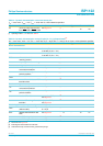
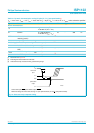
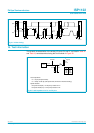
Overcurrent input: OCn; power switch output: PSWn.
Reference voltage for overcurrent sensing: V
CC
(bus-powered mode) or V
SP/BP
(self-powered mode).
Fig 14. Overcurrent trip response timing.
handbook, halfpage
MBL032
V
CC
0 V
overcurrent
input
V
CC
0 V
power switch
output
t
trip
∆V
trip