


Philips Semiconductors
ISP1122
USB stand-alone hub
Product specification Rev. 03 — 29 March 2000 3 of 48
9397 750 07002
© Philips Electronics N.V. 2000. All rights reserved.
5. Pinning information
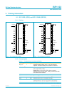
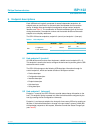
5.1 ISP1122D (SO32) and ISP1122NB (SDIP32)
5.1.1 Pinning
5.1.2 Pin description
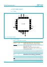
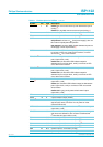
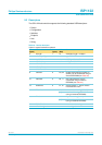
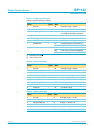
Fig 2. Pin configuration SO32. Fig 3. Pin configuration SDIP32.
handbook, halfpage
ISP1122D
MGR772
1
2
3
4
5
6
7
8
9
10
11
12
13
14
15
16
32
31
30
29
28
27
26
25
24
23
22
21
20
19
18
17
V
reg(3.3)
GND
DM3
DP3
V
CC
DM4
DP4
DP2
DM2
DP0
DP1
DM1
DM0
DP5
DM5
INDV/SDA
OPTION/SCL
XTAL2
XTAL1
PSW1/GL1
RESET
PSW5/GL5/GPSW
PSW4/GL4PSW3/GL3
HUBGL
SP/BP
OC5/GOC
PSW2/GL2
OC1
OC2
OC3
OC4
handbook, halfpage
ISP1122NB
MGR773
1
2
3
4
5
6
7
8
9
10
11
12
13
14
15
16
32
31
30
29
28
27
26
25
24
23
22
21
20
19
18
17
V
reg(3.3)
GND
DM3
DP3
V
CC
DM4
DP4
DP2
DM2
DP0
DP1
DM1
DM0
DP5
DM5
INDV/SDA
OPTION/SCL
XTAL2
XTAL1
PSW1/GL1
RESET
PSW5/GL5/GPSW
PSW4/GL4PSW3/GL3
HUBGL
SP/BP
OC5/GOC
PSW2/GL2
OC1
OC2
OC3
OC4
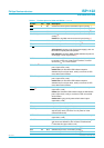
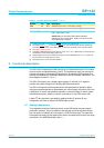
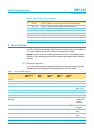
Table 2: Pin description for SO32 and SDIP32
Symbol
[1]
Pin Type Description
V
reg(3.3)
[2]
1 - regulated supply voltage (3.3 V ± 10%) from internal
regulator; used to connect pull-up resistor on DP0 line
PSW2/GL2
[3]
2Omodes 4 to 6: power switch control output for downstream
port 2 (open-drain, 6 mA)
modes 0 to 3, 7: GoodLink LED indicator output for
downstream port 2 (open-drain, 6 mA); to connect an LED
use a 330 Ω series resistor
GND 3 - ground supply
DM3 4 AI/O downstream port 3 D− connection (analog)
[4]
DP3 5 AI/O downstream port 3 D+ connection (analog)
[4]
V
CC
6 - supply voltage; connect to USB supply V
BUS
(bus-powered or
hybrid-powered) or to local supply V
DD
(self-powered)
OC1 7 AI/I overcurrent sense input for downstream port 1 (analog
[5]
)