


Philips Semiconductors
ISP1122
USB stand-alone hub
Product specification Rev. 03 — 29 March 2000 37 of 48
9397 750 07002
© Philips Electronics N.V. 2000. All rights reserved.
[1] f
SCL
=
1
⁄
64
f
XTAL
.
[2] Rise time is determined by C
b
and pull-up resistor value R
p
(typ. 4.7 kΩ).
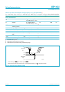
Full-speed timing symbols have a subscript prefix ‘F’, low-speed timings a prefix ‘L’.
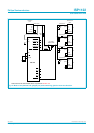
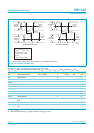
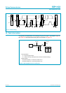
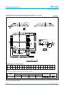
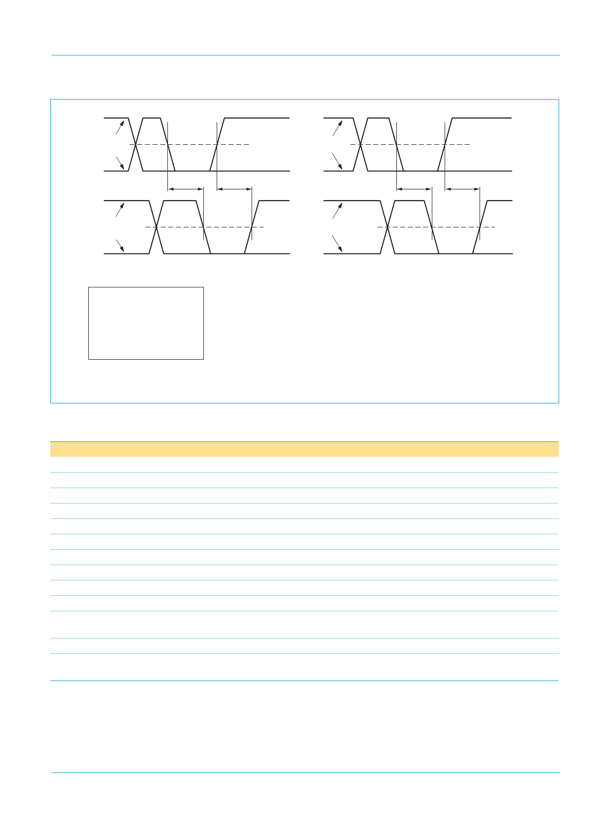
Fig 20. Hub EOP delay and EOP skew.
h
andbook, full pagewidth
MGR778
t
EOP+
t
EOP−
t
EOP+
t
EOP−
crossover
point
extended
crossover
point
extended
EOP delay:
t
EOP
= max (t
EOP−
, t
EOP+
)
EOP delay relative to t
HDD
:
t
EOPD
= t
EOP
− t
HDD
EOP skew:
t
HESK
= t
EOP+
− t
EOP−
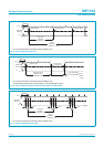
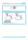
(A) downstream EOP delay (B) upstream EOP delay
upstream
differential
data lines
downstream
port
crossover
point
extended
crossover
point
extended
upstream
end of cable
downstream
differential
data lines
+3.3 V
0 V
+3.3 V
0 V
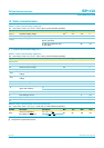
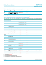
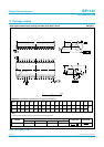
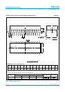
Table 34: Dynamic characteristics: I
2
C-bus pins (SDA, SCL)
V
CC
and T
amb
within recommended operating range; V
DD
=
+5 V; V
SS
=V
GND
; V
IL
and V
IH
between V
SS
and V
DD
.
Symbol Parameter Conditions Min Typ Max Unit
f
SCL
SCL clock frequency f
XTAL
= 6 MHz 0 93.75
[1]
100 kHz
t
BUF
bus free time 4.7 - - µs
t
SU;STA
START condition set-up time 250 - - ns
t
HD;STA
hold time START condition 4.0 - - µs
t
LOW
SCL LOW time 4.7 - - µs
t
HIGH
SCL HIGH time 4.0 - - µs
t
r
SCL and SDA rise time
[2]
- - 1000 ns
t
f
SCL and SDA fall time - - 300 ns
t
SU;DAT
data set-up time 250 - - ns
t
HD;DAT
data hold time 0 - - µs
t
VD;DAT
SCL LOW to data out valid
time
- - 0.4 µs
t
SU;STO
STOP condition set-up time 4.0 - - µs
C
b
capacitive load for each bus
line
- - 400 pF