


Philips Semiconductors
ISP1122
USB stand-alone hub
Product specification Rev. 03 — 29 March 2000 25 of 48
9397 750 07002
© Philips Electronics N.V. 2000. All rights reserved.
The ISP1122 overcurrent detection circuit has been designed with a nominal trip
voltage (∆V
trip
) of 85 mV. This gives a typical trip current of approximately 850 mA for
a power switch with an on-resistance of 100 mΩ
1
.
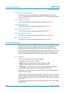
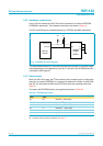
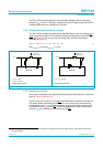
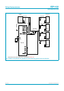
12.3 Tuning the overcurrent trip voltage
The ISP1122 trip voltage can optionally be adjusted through external components to
set the desired trip current. This is done by inserting tuning resistors at pins SP/BP or
OCn (see Figure 9). R
tu
tunes up the trip voltage ∆V
trip
and R
td
tunes it down
according to Equation 1.
(1)
with I
ref(nom)
=5µA and I
OC(nom)
= 0.5 µA.
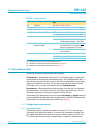
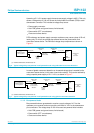
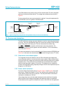
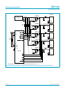
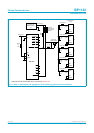
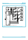
12.4 Reference circuits
Some typical examples of port power switching and overcurrent detection modes are
given in Figure 10 to Figure 13.
The RC circuit (47 kΩ and 0.1 µF) around the PMOS switch provides for soft turn-on.
The series resistor connecting the SP/BP pin to V
CC
tunes up the overcurrent trip
voltage slightly (see Figure 9). In the schematic diagram the resistor separates the
net names for pins V
CC
and SP/BP. This allows an automatic router to use a wide
trace for V
CC
and a narrow trace to connect pin SP/BP.
1. The following PMOS power switches have been tested to work well with the ISP1122: Philips PHP109, Vishay Siliconix Si2301DS,
Fairchild FDN338P.
∆V
trip
∆V
trip intrinsic()
I
ref
R
tu
⋅ I
OC
R
td
⋅–+=
I
ref(nom)
=5µA
I
OC(nom)
= 0.5 µA
I
OC(nom)
= 0.5 µA
a. Self-powered mode. b. Bus-powered mode.
Fig 9. Tuning the overcurrent trip voltage.
handbook, halfpage
MBL042
V
CC
I
ref
R
tu
R
td
low-ohmic
PMOS switch
V
CC
SP/BP
ISP1122
OCn
I
OC
handbook, halfpage
MBL043
V
BUS
R
td
low-ohmic
PMOS switch
V
CC
SP/BP
ISP1122
OCn
I
OC