Philips Semiconductors
ISP1122
USB stand-alone hub
Product specification Rev. 03 — 29 March 2000 38 of 48
9397 750 07002
© Philips Electronics N.V. 2000. All rights reserved.
16. Test information
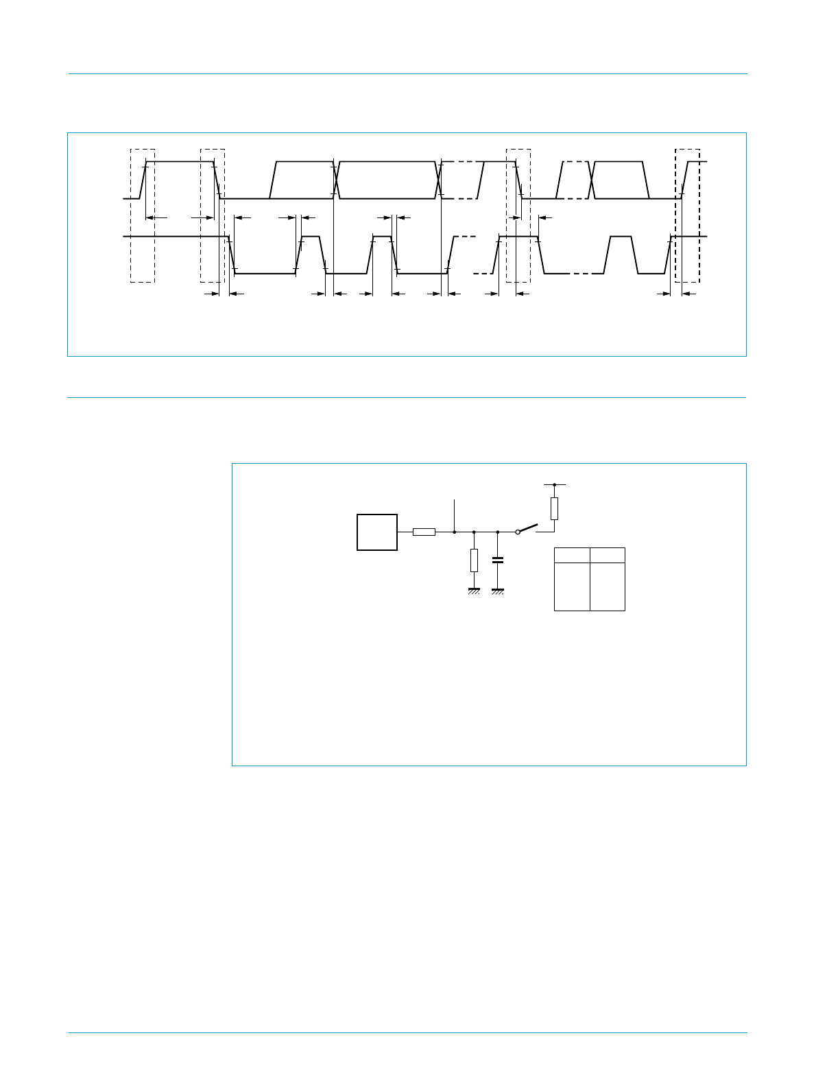
The dynamic characteristics of the analog I/O ports (D+ and D−) as listed in Table 32
and Table 33, were determined using the circuit shown in Figure 22.
Fig 21. I
2
C-bus timing.
h
andbook, full pagewidth
P
S S
P
MGR779
t
HD;STA
t
BUF
t
HD;STA
t
SU;STA
t
SU;DAT
t
f
t
HIGH
t
SU;STO
t
r
t
HD;STA
t
LOW
SDA
SCL
Load capacitance:
C
L
= 50 pF (full-speed mode)
C
L
= 200 pF or 600 pF (low-speed mode, minimum or maximum timing).
Speed selection:
full-speed mode (FS): 1.5 kΩ pull-up resistor on D+
low-speed mode (LS): 1.5 kΩ pull-up resistor on D−.
Fig 22. Load impedance for D+ and D- pins.
MGR775
handbook, halfpage
S1
S1
test point
test
closed
closed
open
open
D−/LS
D+/LS
D−/FS
D+/FS
C
L
V
reg(3.3)
15 kΩ
R
PU
1.5 kΩ
20 Ω
D.U.T.


