


Philips Semiconductors
ISP1122
USB stand-alone hub
Product specification Rev. 03 — 29 March 2000 8 of 48
9397 750 07002
© Philips Electronics N.V. 2000. All rights reserved.
[1] Symbol names with an overscore (e.g. NAME) indicate active LOW signals.
[2] The voltage at pin V
reg(3.3)
is gated by the RESET pin. This allows fully self-powered operation by
connecting RESET to V
BUS
(+5 V USB supply). If V
BUS
is lost upstream port D+ will not be driven.
[3] See Table 4 “Mode selection”.
[4] To disable a downstream port connect both D+ and D− to V
CC
via a 1 MΩ resistor; unused ports must
be disabled in reverse order starting from port 5.
[5] Analog detection circuit can be switched off using an external EEPROM, see Table 23; in this case,
the pin functions as a logic input (TTL level).
[6] Downstream ports 1 and 2 cannot be disabled.
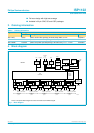
6. Functional description
The ISP1122 is a stand-alone USB hub with up to 5 downstream ports. The number
of ports can be configured between 2 and 5. The downstream ports can be used to
connect low-speed or full-speed USB peripherals. All standard USB requests from
the host are handled by the hardware without the need for firmware intervention. The
block diagram is shown in Figure 1.
The ISP1122 requires only a single supply voltage. An internal 3.3 V regulator
provides the supply voltage for the analog USB data transceivers.
The ISP1122 supports both bus-powered and self-powered hub operation. When
using bus-powered operation a downstream port cannot supply more than 100 mA to
a peripheral. In case of self-powered operation an external supply is used to power
the downstream ports, allowing a current consumption of max. 500 mA per port.
A basic I
2
C-bus interface is provided for reading vendor ID, product ID and
configuration bits from an external EEPROM upon a reset.
6.1 Analog transceivers
The integrated transceiver interfaces directly to the USB cables through external
termination resistors. They are capable of transmitting and receiving serial data at
both ‘full-speed’ (12 Mbit/s) and ‘low-speed’ (1.5 Mbit/s) data rates. The slew rates
are adjusted according to the speed of the device connected and lie within the range
mentioned in the
USB Specification Rev. 1.1
.
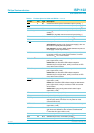
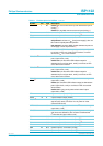
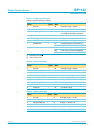
DM2 26 AI/O downstream port 2 D− connection (analog)
[6]
DP2 27 AI/O downstream port 2 D+ connection (analog)
[6]
PSW1/GL1
[3]
28 O modes 4 to 6: power switch control output for downstream
port 1 (open-drain, 6 mA)
modes 0 to 3, 7: GoodLink LED indicator output for
downstream port 1 (open-drain, 6 mA); to connect an LED
use a 330 Ω series resistor
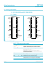
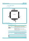
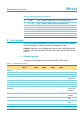
Table 3: Pin description for LQFP32
…continued
Symbol
[1]
Pin Type Description