


Philips Semiconductors
ISP1521
Hi-Speed USB hub controller
Product data Rev. 03 — 24 November 2004 15 of 53
9397 750 13702
© Koninklijke Philips Electronics N.V. 2004. All rights reserved.
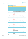
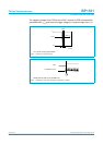
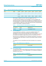
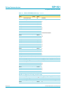
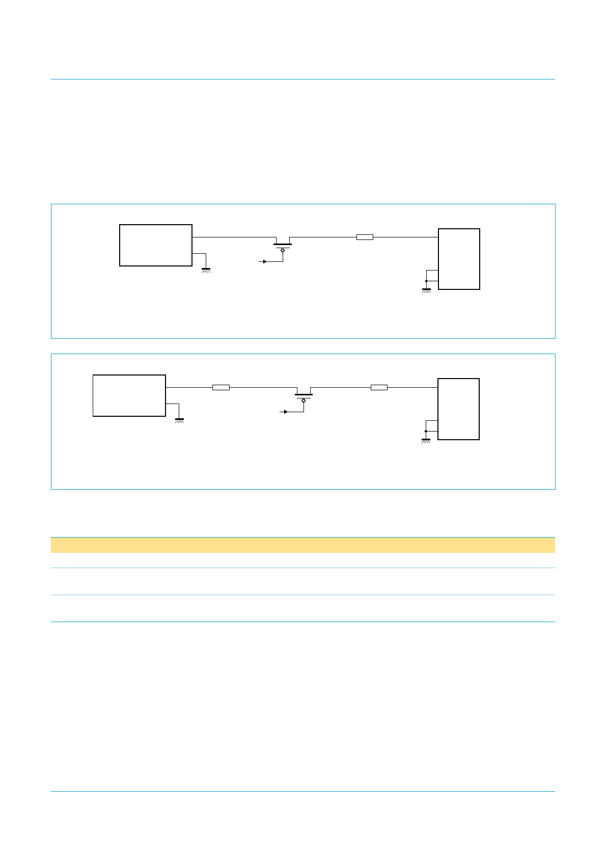
For global overcurrent detection, an increased voltage drop is needed for the
overcurrent sense device (in this case, a low-ohmic resistor). This can be realized by
using a special power supply of 5.1 V ± 3 %, as shown in Figure 6.
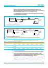
The PCB resistance may cause a drop of 25 mV, which leaves 75 mV for the power
switch and overcurrent sense device.
PSWn_N pins have integrated weak pull-up resistors inside the chip.
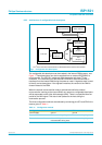
9.1.3 Overcurrent protection mode
The ISP1521 supports all overcurrent protection modes: none, global and individual.
No overcurrent protection mode reporting is selected when pin NOOC = HIGH.
Global and individual overcurrent protection modes are selected using pins PSWn_N,
following the power switching modes selection scheme; seeTable 6.
For the global overcurrent protection mode, only PSW1_N and OC1_N are active;
that is, in this mode, the remaining overcurrent indicator pins are disabled. To inhibit
the analog overcurrent detection, the OC_N pins must be connected to V
REF(5V0)
.
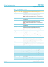
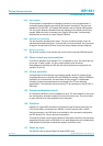
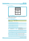
(1) Includes PCB traces, ferrite beads, and so on.
Fig 5. Typical voltage drop components in the self-powered mode using individual overcurrent detection.
5 V
POWER SUPPLY
± 3 % regulated
−
+
4.85 V (min)
004aaa264
low-ohmic
PMOS switch
ISP1521
power switch
V
BUS
D+
D−
GND
SHIELD
4.75 V (min)
downstream
port
connector
hub board
resistance
voltage drop
25 mV
voltage drop
75 mV
(1)
(PSWn_N)
(1) Includes PCB traces, ferrite beads, and so on.
Fig 6. Typical voltage drop components in the self-powered mode using global overcurrent detection.
5.1 V KICK-UP
POWER SUPPLY
± 3 % regulated
−
+
4.95 V(min)
004aaa265
low-ohmic
PMOS switch
V
BUS
D+
D−
GND
SHIELD
4.75 V(min)
downstream
port
connector
hub board
resistance
voltage drop
25 mV
voltage drop
75 mV
low-ohmic
sense resistor
for overcurrent
detection
voltage drop
100 mV
(1)
ISP1521 power
switch
(PSWn_N)
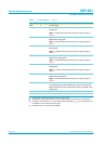
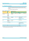
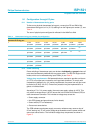
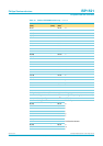
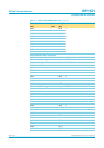
Table 5: Power switching mode: pin configuration
Power switching mode PSW1_N PSW2_N PSW3_N PSW4_N PSW5_N PSW6_N PSW7_N
None ground ground ground ground ground ground ground
Ganged internal
pull-up
ground ground ground ground ground ground
Individual internal
pull-up
internal
pull-up
internal
pull-up
internal
pull-up
internal
pull-up
internal
pull-up
internal
pull-up