


Philips Semiconductors
ISP1521
Hi-Speed USB hub controller
Product data Rev. 03 — 24 November 2004 17 of 53
9397 750 13702
© Koninklijke Philips Electronics N.V. 2004. All rights reserved.
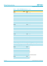
9.2 Device descriptors and string descriptors settings using I
2
C-bus
9.2.1 Background information on I
2
C-bus
The I
2
C-bus is suitable for bi-directional communication between ICs or modules. It
consists of two bi-directional lines: SDA for data signals and SCL for clock signals.
Both these lines must be connected to a positive supply voltage through a pull-up
resistor.
The basic I
2
C-bus protocol is defined as:
• Data transfer is initiated only when the bus is not busy.
• Changes in the data line occur when the clock is LOW and must be stable when
the clock is HIGH. Any changes in data lines when the clock is HIGH will be
interpreted as control signals.
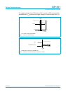
Different conditions on I
2
C-bus: The I
2
C-bus protocol defines the following
conditions:
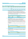
Not busy — both SDA and SCL remain HIGH
START — a HIGH-to-LOW transition on SDA, while SCL is HIGH
STOP — a LOW-to-HIGH transition on SDA, while SCL is HIGH
Data valid — after a START condition, data on SDA must be stable for the duration of
the HIGH period of SCL.
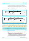
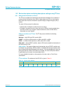
Data transfer: The master initiates each data transfer using a START condition and
terminates it by generating a STOP condition. To facilitate the next byte transfer, each
byte of data must be acknowledged by the receiver. The acknowledgement is done by
pulling the SDA line LOW on the ninth bit of the data. An extra clock pulse needs to
be generated by the master to accommodate this bit.
For more detailed information on the operation of the bus, refer to
The I
2
C-bus
specification
.
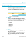
I
2
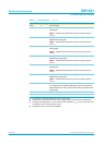
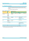
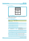
C-bus address: The address of the ISP1521 is given in Table 1 0.
Table 10: I
2
C-bus slave address
MSB Slave address LSB
Bit A7 A6 A5 A4 A3 A2 A1 R/W
Value 00110100/1