


Philips Semiconductors
ISP1521
Hi-Speed USB hub controller
Product data Rev. 03 — 24 November 2004 18 of 53
9397 750 13702
© Koninklijke Philips Electronics N.V. 2004. All rights reserved.
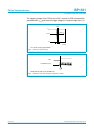
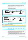
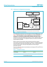
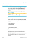
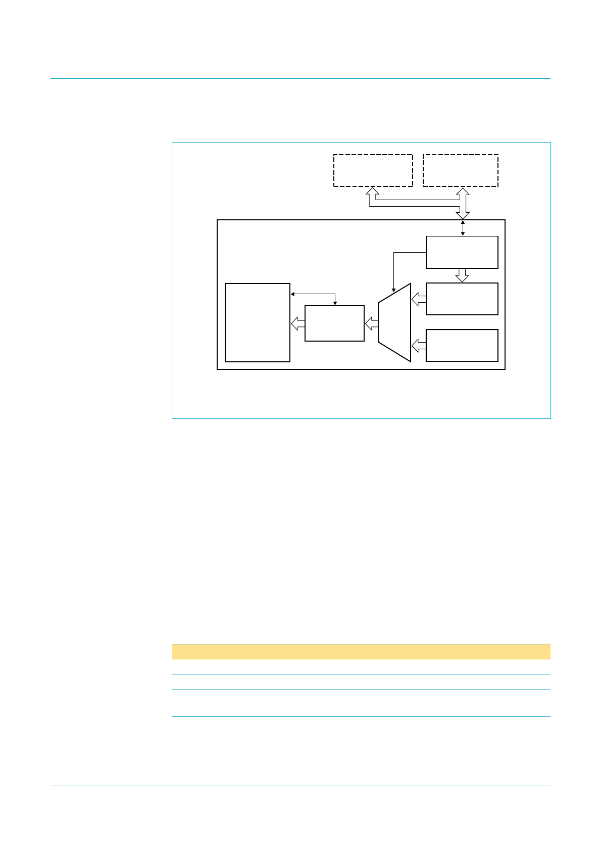
9.2.2 Architecture of configurable hub descriptors
The configurable hub descriptors can be masked in the internal ROM memory; see
Figure 7. These descriptors can also be supplied from an external EEPROM or a
microcontroller. The ISP1521 implements both the master and slave I
2
C-bus
controllers. The information from the external EEPROM or the microcontroller is
transferred into the internal RAM during the power-on reset. A signature word is used
to identify correct descriptors. If the signature matches, the content of the RAM is
chosen instead of the ROM.
When the external microcontroller mode is selected and while the external
microcontroller is writing to the internal RAM, any request to configurable descriptors
will be responded to with a Not AcKnowledge (NAK). There is no specified time-out
period for the NAK signal. This data is then passed to the host during the
enumeration process.
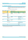
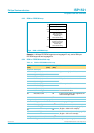
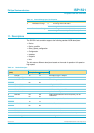
The three configuration methods are selected by connecting pins SCL and SDA in the
manner given in Table 1 1.
The I
2
C-bus cannot be shared between the EEPROM and the external microcontroller.
Fig 7. Configurable hub descriptors.
Table 11: Configuration method
Configuration method SCL SDA
Internal ROM ground ground
External EEPROM 2.2 kΩ to 4.7 kΩ pull-up 2.2 kΩ to 4.7 kΩ pull-up
External microcontroller driven LOW by the
microcontroller during reset
2.2 kΩ to 4.7 kΩ pull-up
MLD711
MICROCONTROLLER SERIAL EEPROM
MASTER/SLAVE
I
2
C-BUS INTERFACE
signature
match
RAM
(256 bytes)
DESCRIPTOR
GENERATOR
INTERFACE
ROM
(256 bytes)
MUX
HUB CORE
I
2
C-bus