


Philips Semiconductors
ISP1521
Hi-Speed USB hub controller
Product data Rev. 03 — 24 November 2004 6 of 53
9397 750 13702
© Koninklijke Philips Electronics N.V. 2004. All rights reserved.
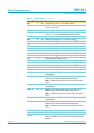
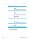
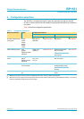
DP0 4 AI/O upstream facing port 0 D+ connection (analog)
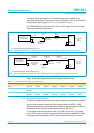
RPU 5 AI pull-up resistor connection; connect this pin through a resistor of
1.5 kΩ±5 % to 3.3 V
GND 6 - ground supply
RREF 7 AI reference resistor connection; connect this pin through a resistor
of 12 kΩ±1 % to an analog band gap ground reference
GND 8 - ground supply
DM5 9 AI/O downstream facing port 5 D− connection (analog)
[3]
DP5 10 AI/O downstream facing port 5 D+ connection (analog)
[3]
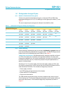
V
CC1
11 - analog supply voltage 1 (3.3 V)
GND 12 - ground supply
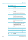
V
CC4
13 - crystal and PLL supply voltage 4 (3.3 V)
GND 14 - ground supply
DM6 15 AI/O downstream facing port 6 D− connection (analog)
[3]
DP6 16 AI/O downstream facing port 6 D+ connection (analog)
[3]
V
CC2
17 - transceiver supply voltage 2 (3.3 V)
GND 18 - ground supply
DM1 19 AI/O downstream facing port 1 D− connection (analog)
[4]
DP1 20 AI/O downstream facing port 1 D+ connection (analog)
[4]
TEST_LOW 21 - connect to GND
TEST_HIGH 22 - connect to 5.0 V through a 10 kΩ resistor
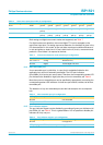
OC1_N 23 AI/I overcurrent sense input for downstream facing port 1
(analog/digital)
PSW1_N 24 I/O output — power switch control output (open-drain) with an
internal pull-up resistor for downstream facing port 1
input — function of the pin when used as an input is given in
Table 5
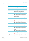
OC6_N 25 AI/I overcurrent sense input for downstream facing port 6
(analog/digital)
PSW6_N 26 I/O output — power switch control output (open-drain) with an
internal pull-up resistor for downstream facing port 6
input — function of the pin when used as an input is given in
Table 5
OC5_N 27 AI/I overcurrent sense input for downstream facing port 5
(analog/digital)
PSW5_N 28 I/O output — power switch control output (open-drain) with an
internal pull-up resistor for downstream facing port 5
input — function of the pin when used as an input is given in
Table 5
GND 29 - ground supply
V
CC3
30 - digital supply voltage 3 (3.3 V)
V
REF(5V0)
31 - reference voltage (5 V ± 5 %); used to power internal pull-up
resistors of PSWn_N pins and also for the analog overcurrent
detection
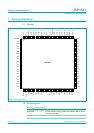
Table 2: Pin description
[1]
…continued
Symbol
[2]
Pin Type Description