


Philips Semiconductors
ISP1521
Hi-Speed USB hub controller
Product data Rev. 03 — 24 November 2004 9 of 53
9397 750 13702
© Koninklijke Philips Electronics N.V. 2004. All rights reserved.
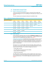
[1] The maximum current the ISP1521 can sink on a pin is 8 mA.
[2] Symbol names ending with underscore N (for example, NAME_N) represent active LOW signals.
[3] To disable a downstream port n, connect both pins DPn and DMn to V
CC
(3.3 V); unused ports must
be disabled in reverse order starting from port 7.
[4] Downstream ports 1 and 2 cannot be disabled.
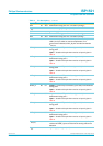
GND 71 - ground supply
GRN1_N 72 I/O output — green LED port indicator (open-drain) for downstream
facing port 1
input — function of the pin when used as an input is given in
Table 9
AMB1_N 73 I/O output — amber LED port indicator (open-drain) for
downstream facing port 1
input — function of the pin when used as an input is given in
Table 8
GRN6_N 74 I/O output — green LED port indicator (open-drain) for downstream
facing port 6
input — function of the pin when used as an input is given in
Table 9
AMB6_N 75 I/O output — amber LED port indicator (open-drain) for
downstream facing port 6
input — function of the pin when used as an input is given in
Table 8
GRN5_N 76 I/O output — green LED port indicator (open-drain) for downstream
facing port 5
input — function of the pin when used as an input is given in
Table 9
AMB5_N 77 I/O output — amber LED port indicator (open-drain) for
downstream facing port 5
input — function of the pin when used as an input is given in
Table 8
HUBGL_N 78 O hub GoodLink LED indicator output; the LED is off until the hub
is configured; a transaction between the host and the hub will
blink the LED off for 100 ms; this LED is off in the suspend mode
(open-drain)
SCL 79 I/O I
2
C-bus clock (open-drain); see Table 11
SDA 80 I/O I
2
C-bus data (open-drain); see Tabl e 11
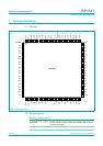
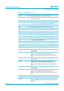
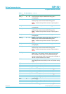
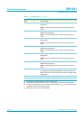
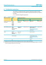
Table 2: Pin description
[1]
…continued
Symbol
[2]
Pin Type Description