


Philips Semiconductors
ISP1521
Hi-Speed USB hub controller
Product data Rev. 03 — 24 November 2004 16 of 53
9397 750 13702
© Koninklijke Philips Electronics N.V. 2004. All rights reserved.
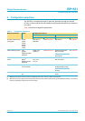
Both analog and digital overcurrent modes are supported; see Tabl e 7 .
For digital overcurrent detection, the normal digital TTL level is accepted on the
overcurrent input pins. For analog overcurrent detection, the threshold is given in the
DC characteristics. In this mode, to filter out false overcurrent conditions because of
in rush and spikes, a dead time of 15 ms is built into the IC, that is, overcurrent must
persist for 15 ms before it is reported to the host.
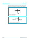
9.1.4 Non-removable port
A non-removable port, by definition, is a port that is embedded inside the hub
application box and is not externally accessible. The LED port indicators
(pins AMBn_N) of such a port are not used. Therefore, the corresponding amber LED
port indicators are disabled to signify that the port is non-removable; see Tabl e 8 .
More than one non-removable port can be specified by appropriately connecting the
corresponding amber LED indicators. At least one port should, however, be left as a
removable port.
The detection of any non-removable port sets the hub descriptor into a compound
hub.
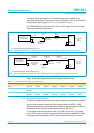
9.1.5 Port indicator support
The port indicator support can be disabled by grounding all green port indicators (all
pins GRNn_N); see Table 9. This is a global feature. It is not possible to disable port
indicators for only one port.
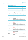
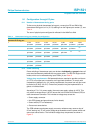
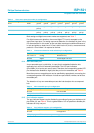
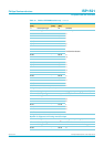
Table 6: Overcurrent protection mode pin configuration
Power switching mode NOOC PSW1_N PSW2_N PSW3_N PSW4_N PSW5_N PSW6_N PSW7_N
None HIGH ground ground ground ground ground ground ground
Global LOW internal
pull-up
ground ground ground ground ground ground
Individual LOW internal
pull-up
internal
pull-up
internal
pull-up
internal
pull-up
internal
pull-up
internal
pull-up
internal
pull-up
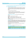
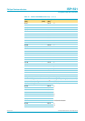
Table 7: Overcurrent detection mode selection pin configuration
Pin ADOC Mode selection Description
3.3 V or 5.0 V analog threshold ∆V
trip
Ground digital normal digital TTL level
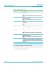
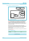
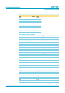
Table 8: Non-removable port pin configuration
AMBn_N (n=1to7) Non-removable port
Ground non-removable
Pull-up with amber LED removable
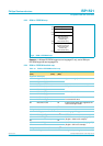
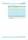
Table 9: Port indicator support: pin configuration
GRN1_N to GRN7_N Port indicator support
Ground not supported
LED pull-up green LED for at least one port supported