


Philips Semiconductors
ISP1521
Hi-Speed USB hub controller
Product data Rev. 03 — 24 November 2004 40 of 53
9397 750 13702
© Koninklijke Philips Electronics N.V. 2004. All rights reserved.
[1] Excluding the first transition from idle state.
[2] Characterized only, not tested. Limits guaranteed by design.
[1] Excluding the first transition from idle state.
[2] Characterized only, not tested. Limits guaranteed by design.
t
FSOP
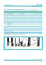
data bit width distortion after SOP see Figure 14 −5 - +5 ns
t
FEOPD
hub EOP delay relative to t
HDD
see Figure 15 0 - 15 ns
t
FHESK
hub EOP output width skew see Figure 15 −15 - +15 ns
Table 44: Dynamic characteristics: full-speed source electrical characteristics
…continued
V
CC
= 3.0 V to 3.6 V; T
amb
=
−
40
°
Cto+70
°
C; test circuit Figure 22; unless otherwise specified.
Symbol Parameter Conditions Min Typ Max Unit
Table 45: Dynamic characteristics: low-speed source electrical characteristics
V
CC
= 3.0 V to 3.6 V; T
amb
=
−
40
°
Cto+70
°
C; test circuit Figure 22; unless otherwise specified.
Symbol Parameter Conditions Min Typ Max Unit
Driver characteristics
t
LR
rise time 75 - 300 ns
t
LF
fall time 75 - 300 ns
t
LRFM
differential rise and fall time
matching
[1]
80 - 125 %
V
CRS
output signal crossover voltage
[1][2]
1.3 - 2.0 V
Hub timing (downstream ports configured as full-speed)
t
LHDD
hub differential data delay see Figure 14 - - 300 ns
t
LSOP
data bit width distortion after SOP see Figure 14
[2]
−60 - +60 ns
t
LEOPD
hub EOP delay relative to t
HDD
see Figure 15
[2]
0 - 200 ns
t
LHESK
hub EOP output width skew see Figure 15
[2]
−300 - +300 ns
T
PERIOD
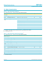
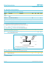
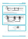
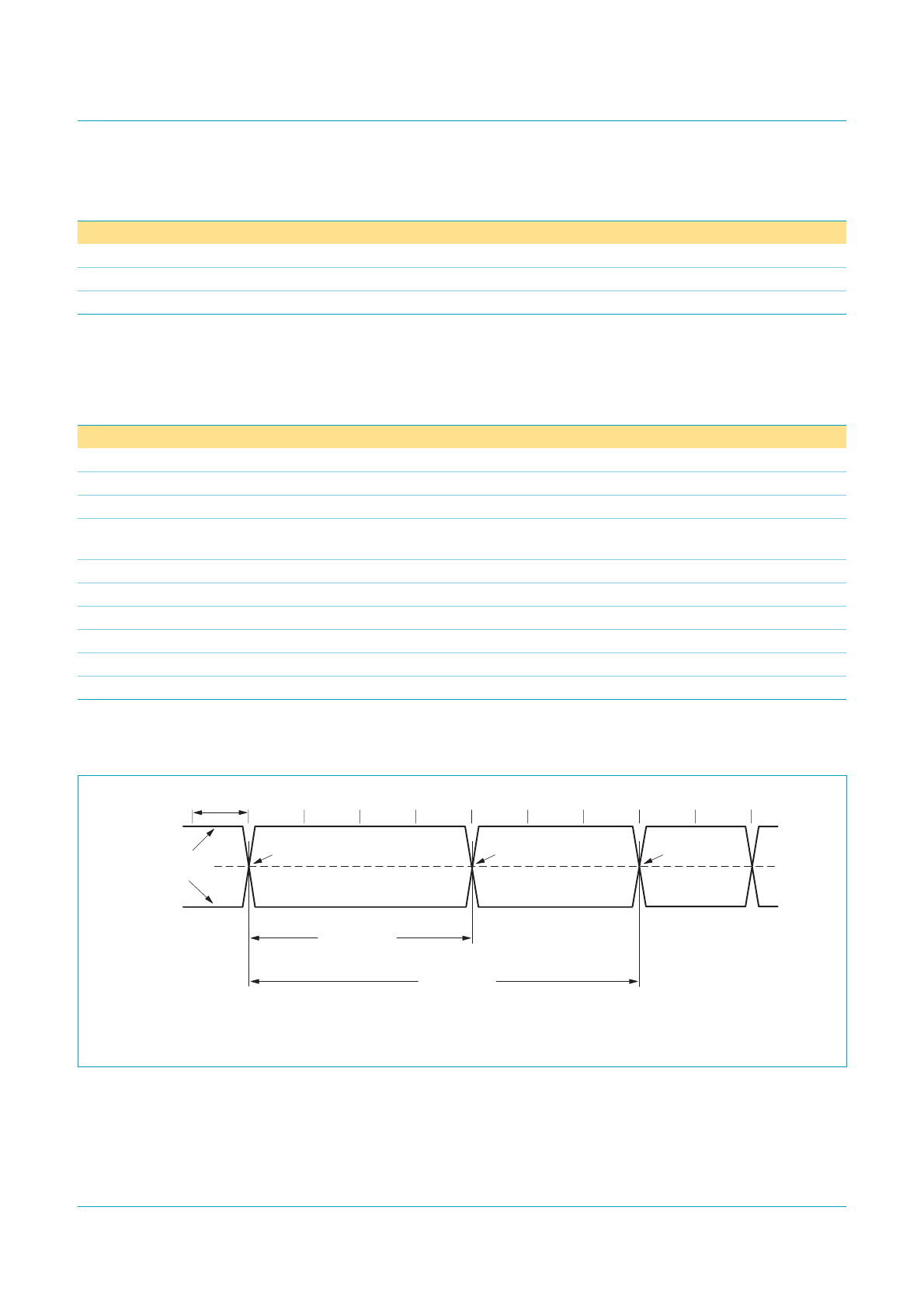
is the bit duration corresponding with the USB data rate.
Fig 10. Source differential data jitter.
mgr870
T
PERIOD
differential
data lines
crossover point
crossover point crossover point
consecutive
transitions
N × T
PERIOD
+ t
DJ1
paired
transitions
N × T
PERIOD
+ t
DJ2
+3.3 V
0 V