


Installation Instructions 3 - 7
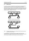
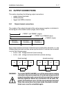
3.5 OUTPUT CONNECTIONS
This section describes the followin
g
output connections:
• output channel terminals
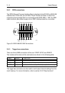
• GPIB connector
•tri
gg
er bus SMB connectors
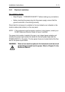
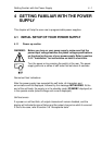
3.5.1 Output channel connections
The number of the output channels of the various power supplies is indicated in
the last fi
g
ure of the model number (sin
g
le, dual or triple).
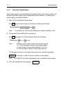
Every output channel connector is identical and consists of four terminals, i.e., two
Volta
g
e output terminals and two sense input terminals. A load can be connected
in one of the followin
g
ways:
• to the + and - volta
g
e terminals (local sensin
g
)
• to the + and - volta
g
e and sense terminals (remote sensin
g
)
WARNING: To prevent SHOCK HAZARD, turn off the power before makin
g
rear output channel connections. All wires and straps must be
properly insulated, and connected with terminal block screws
securely ti
g
htened. Before any connection can be made, the
plastic terminal block cover must be unscrewed and removed.
When the connections have been made, the plastic terminal
block cover must be reinstalled a
g
ain.
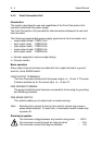
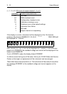
= PM2811 and PM2831 (sin
g
le)
= PM2812 and PM2832 (dual)
= PM2813 (triple)
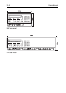
OUTPUTOUTPUTOUTPUT
CHANNEL 1 CHANNEL 2 CHANNEL 3
- S- V+ V+ S
load
- S- V+ V+ S
load
(local sensin
g
) (remote sensin
g
)