


Usin
g
your Pro
g
rammable Power Supply 5 - 15
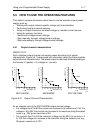
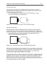
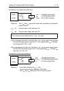
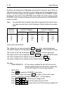
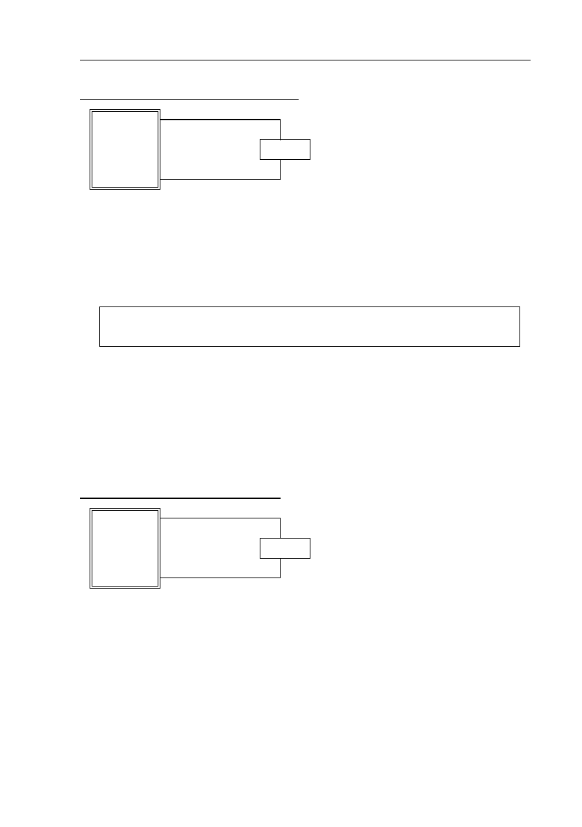
Example for a variable load resistance:
Required: The V
set
and I
set
parameter have been coupled for the selected
output channel.
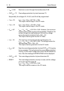
•I
Set
= 1A Pro
g
rammed current becomes 1A.
•V
set
= 8V Pro
g
rammed volta
g
e becomes 8V.
•If R
load
increases from 8Ω to 16Ω, then R
load
> R
c
, so the output channel
g
oes
into the CV mode (refer to fi
g
ure 5.5.7). This means that V
load
= 8V and
I
load
becomes 8V/16Ω = 0.5A.
•If R
load
decreases from 8Ω to 4Ω, then R
load
< R
c
, so the output channel
g
oes
into the CC mode (refer to fi
g
ure 5.5.7). This means that I
load
= 1A and V
load
becomes 1A x 4Ω = 4V.
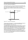
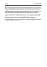
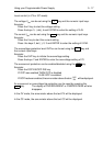
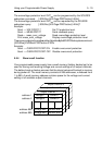
Example for a fixed load resistance:
Required: - Fixed load resistance R
load
= 10Ω.
- Overcurrent protection disabled (OCP DIS).
- The V
set
and I
set
parameter have not been coupled.
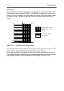
power
output
+
-
load
+
-
V
set
OVP
set
I
set
V
set
= Volta
g
e pro
g
rammed
I
set
= Current pro
g
rammed
R
load
= 2Ω to 20Ω (variable)
The crossover point resistance R
c
= V
set
/ I
set
= 8Ω.
power
output
+
-
load
+
-
V
set
OVP
set
I
set
V
set
= Volta
g
e pro
g
rammed
OVP
set
= OverVolta
g
e pro
g
rammed
I
set
= Current pro
g
rammed