


Gettin
g
Familair with the Power Supply 4 - 7
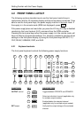
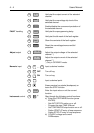
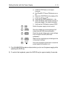
4.3 OUTPUT CHANNEL CONNECTIONS
WARNING: To prevent SHOCK HAZARD, turn off the line power before
makin
g
output channel connections or disable the output
channel concerned. All wires and straps must be properly
insulated, and connected with terminal block screws securely
ti
g
htened. Before any connection can be made, the plastic
terminal block cover must be unscrewed and removed. When
the connections have been made, the plastic terminal block
cover must be secured a
g
ain.
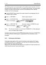
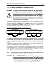
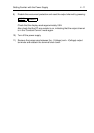
Each output channel has been provided with a set of four terminals. The inner two
have been marked as - V(olta
g
e) and + V(olta
g
e), while the outer two have been
marked as - S(ense) and + S(ense). At delivery the +V and +S, as well as the -V
and -S terminals have been interconnected by straps.
The volta
g
e at the sense terminal(s) equals the pro
g
rammed value. The volta
g
e
at a connected load may differ from the pro
g
rammed value, because of a volta
g
e
drop dependin
g
on the resistance of the wires to the load and the current throu
g
h
the load.
If the volta
g
e drop is ne
g
li
g
ible, the load wires only have to be connected to the
+V and -V terminals. This is called ’local sensin
g
’.
However, if the volta
g
e drop is si
g
nificant, the volta
g
e at the load can differ from
the pro
g
rammed value. To prevent this, the straps between the +V and +S and -
V and -S terminals must be removed and the load wires must also be connected
to the +S and -S terminals. This is called ’remote sensin
g
’.
Note: The terminals have been shielded with a plastic block cover which must
be removed before any connection can be made.
WARNING: To avoid FIRE HAZARD, select a wire lar
g
e enou
g
h to carry
short-circuit current without overheatin
g
. Two factors must be
considered when selectin
g
the wire size for load connections:
- Conductor temperature, i.e., the current-carryin
g
capacity.
- Total volta
g
e drop, i.e., the wire len
g
th and thickness.
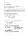
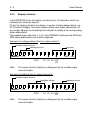
- S- V+ V+ S
load
Rear view of an output channel connected to a load:
- S- V+ V+ S
load
(local sensin
g
) (remote sensin
g
)