


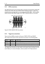

Installation Instructions 3 - 11
3.6.2 Interface check
To perform the GPIB interface check, the power supply must be connected to the
controller via the GPIB; therefore, you need a GPIB interface card + software
GPIB drivers + a pro
g
rammin
g
lan
g
ua
g
e.
The various parts of the followin
g
interface check must be executed sequentially.
Your power supply
g
oes into the remote state when the first command is sent via
the GPIB. However, the results of pro
g
rammed commands can still be monitored
on the display, e.
g
., the readback volta
g
e and current. Also the text REM will be
displayed in the remote state.
The interface check consists of the followin
g
parts:
Check the GPIB address settin
g
under the AUX menu.
send
→
*
IDN? Identification query
read
←
PHILIPS,PM28nn/xy,0,Va.b
Notes: • nn = 11, 12, 13, 31 or 32
• x is the model indication
• y is the hardware version
• a.b = the firmware version
send
→
*
TST? Read result of power on test.
read
←
<response_strin
g
>
IF <response_strin
g
> = 0 THEN test result is correct
ELSE display controller failure
send
→
:TEST:SYSTEM? Selftest power supply query.
read
←
<response_strin
g
>
IF <response_strin
g
> = 0 THEN test result is correct
ELSE the <response_strin
g
> = hardware error number
send
→
:INST:NSEL 1 Select output channel 1 (only for
multiple output models).
send
→
:TEST:INSTRUMENT? Selftest of the output channel 1.
read
←
<response_strin
g
>
IF <response_strin
g
> = 0 THEN test result is correct
ELSE the <response_strin
g
> = hardware error number
Repeat this check for all available output channels.
Note: For meanin
g
of the hardware error numbers, refer to section 3.6.1 "Brief
check" or to "Error Messa
g
es" in the Reference Manual.