


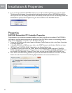

4
EN
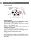
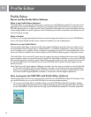
Controller Diagram
Button Descriptions
• Directional pad - Represents UP, DOWN, LEFT, RIGHT and four diagonals. Directional Pad will function as a
POV (Point of View) hat during analog mode.
• Buttons “1”, “2”, “3”, and “4” are default re buttons and are all digital in nature.
• Left and right analog sticks - each contains two axes. Left analog stick controls the X and Y Axis. Right analog
stick controls the Rz and Z axis. Also, there is a “hidden” button “11” and “12” under each stick that is acti-
vated when the analog stick is depressed inward.
• Buttons “5”, “6”, “7”, and “8” are all digital shoulder buttons.
• Analog Mode button - Used to switch the controller from digital to analog mode (and vice versa). Analog mode is
the default mode. The red LED will illuminate when the controller is in analog mode and be off in digital mode.
• The Start and Select buttons are digital buttons (9, 10).
• The Esc button provides the same function as the esc key on your windows keyboard. Note: You must have
installed the mouse and key prole editor software. This button is not MAC compatible.
• The Enter button provides the same function as the Enter key on your windows keyboard. Note: You must
have installed the mouse and key prole editor software. This button is not MAC compatible.
• The Mouse button is used when the mouse and key prole editor emulation software is installed and it will
activate mouse movement mode. Note: This button is not MAC compatible.
Analog Button
Use to switch between digital and analog mode. Analog mode is the default mode. All buttons are accessible in
digital and analog mode. In digital mode, the analog sticks are non-operational and the D-pad digitally controls
the X and Y axis. In the analog mode, the D-pad functions as a POV hat while the left analog stick controls the X
and Y axis. The right analog stick controls the Rz and Z axis. The LED below the Analog button will be illuminated
when Analog mode is on.
Controller Diagram