


10
En
English
Installation and Connections
Installation and Connections
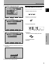
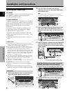
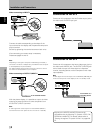
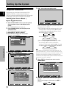
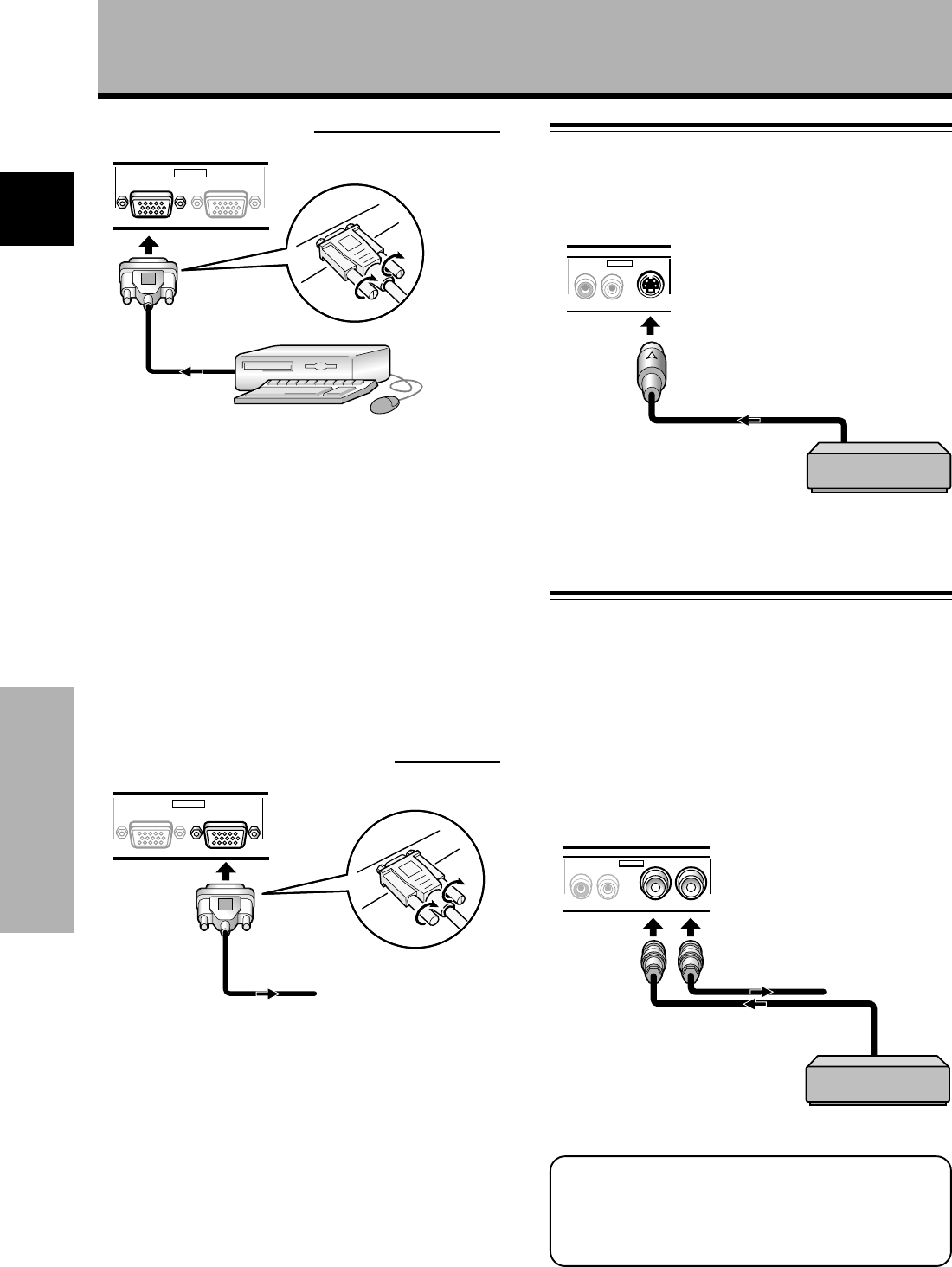
Connection to INPUT3
Connect an AV component that has S-video output jack to
the video card’s S-VIDEO input jack.
Connection to INPUT4
Connect an AV component that has a video output jack to
the video card’s INPUT4 jack. The OUTPUT [INPUT4] jack
can be used to output the video signal to a separate
monitor, recording device or other component with video
input capability.
Note
A video signal will not be output from the OUTPUT [INPUT4] jack
when the main power of this display is off or in standby mode.
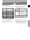
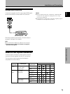
Signals to the INPUT3 and INPUT4 jacks are all
compatible with the following TV systems: NTSC, PAL,
SECAM and 4.43NTSC. For details, please refer to
“Setting the regional TV system format” on pages 26-
27.
AV component
AV component
To a monitor or a
recording device
AUDIO
INPUT4
VIDEO OUTPUT
RL
AUDIO
INPUT3
S-VIDEO
RL
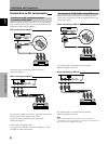
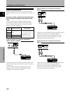
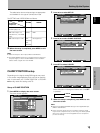
When connecting to INPUT1
ANALOG RGB (ANALOG RGB)
INPUT1
OUTPUT
Connect the cable corresponding to the shape of the
input terminal on the display and the personal computer’s
output terminal.
Secure by tightening the terminal screws on both units.
After connecting, on-screen setup is necessary.
Please see pages 14 and 15.
Note
Depending on the type of computer model being connected, a
conversion connector or adapter etc. provided with the computer
or sold separately may be necessary.
For details, please read your PC’s instruction manual or consult
the maker or nearest dealer of your computer.
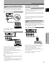
When connecting to OUTPUT (INPUT1)
ANALOG RGB (ANALOG RGB)
INPUT1
OUTPUT
With the plasma display, it is possible to output the video
signal to an external monitor or other component from
the OUTPUT (INPUT1) terminal.
Note
A video signal will not be output from the OUTPUT (INPUT1)
terminal when the main power of this unit is off or in standby.
To an external monitor