


5
En
Part Names and Functions
English
Part Names and Functions
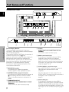
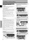
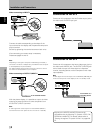
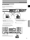
8 Synchronizing signal impedance selector switch
Depending on the connections made at INPUT2, it
may be necessary to set this switch to match the
output impedance of the connected component’s
synchronization signal.
When the output impedance of the component’s
synchronization signal is above 75 Ω, set this switch
to the 2.2 kΩ position (page 9).
9 AUDIO INPUT (Stereo mini jack)
Use to obtain sound when INPUT1, INPUT2 or
INPUT5 is selected.
Connect this jack to the audio output connector of the
device connected to the plasma display’s INPUT1 or
INPUT2, or to the audio output connector of the
device connected to the video card’s INPUT5 (page
12).
0 AUDIO OUTPUT (Stereo mini jack)
Use to output the audio of the selected source
component connected to the plasma display to an AV
amplifier or similar component (page 12).
- MAIN POWER switch
Use to switch the main power of the plasma display
on and off.
= AC INLET
A power cable is furnished with the plasma display;
connect one end of the power cable to this connector,
and the other end to a standard AC power source.
~ SPEAKER (L) terminal
For connection of an external left speaker. Connect a
speaker that has an impedance of 8 -16 Ω.
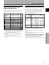
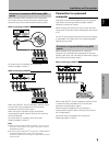
Video Card <PDA-5002> Section
The video card is provided with 3 video input connectors,
1 video output connector, and 2 audio input connectors.
Consult the pages noted in parentheses ( ) for details
regarding connections to the various jacks and
connectors.
! INPUT5 (DVI-D jack)
Use to connect a computer.
Note: This unit does not support the display of
copyguard-protected video signals (page 11).
@ AUDIO INPUT3 (RCA Pin jacks)
Use to obtain sound when INPUT3 is selected.
Connect these jacks to the audio output connectors of
components connected to the video card’s INPUT3
(page 12).
Note: The left audio channel (L) jack is not compatible
with monaural input sources.
# INPUT3 (S-video jack)
For connection of components that have an S-video
output jack such as a video deck, video camera, laser
disc player, or DVD player. (page 10)
$ AUDIO INPUT4 (RCA Pin jacks)
Use to obtain sound when INPUT4 is selected.
Connect these jacks to the audio output connectors of
components connected to the video card’s INPUT4
(page 12).
Note: The left audio channel (L) jack is not compatible
with monaural input sources.
% INPUT4 (BNC jack)
For connection of components that have a composite
video output jack such as a video deck, video camera,
laser disc player, or DVD player (page 10).
^ OUTPUT (INPUT4) (BNC jack)
Use the OUTPUT (INPUT4) jack to output the video
signal to an external monitor or other component.
Note: The video signal will not be output from the
OUTPUT (INPUT4) jack when the main power of this
display is off or in standby mode (page 10).