4
En
Part Names and Functions
English
Part Names and Functions
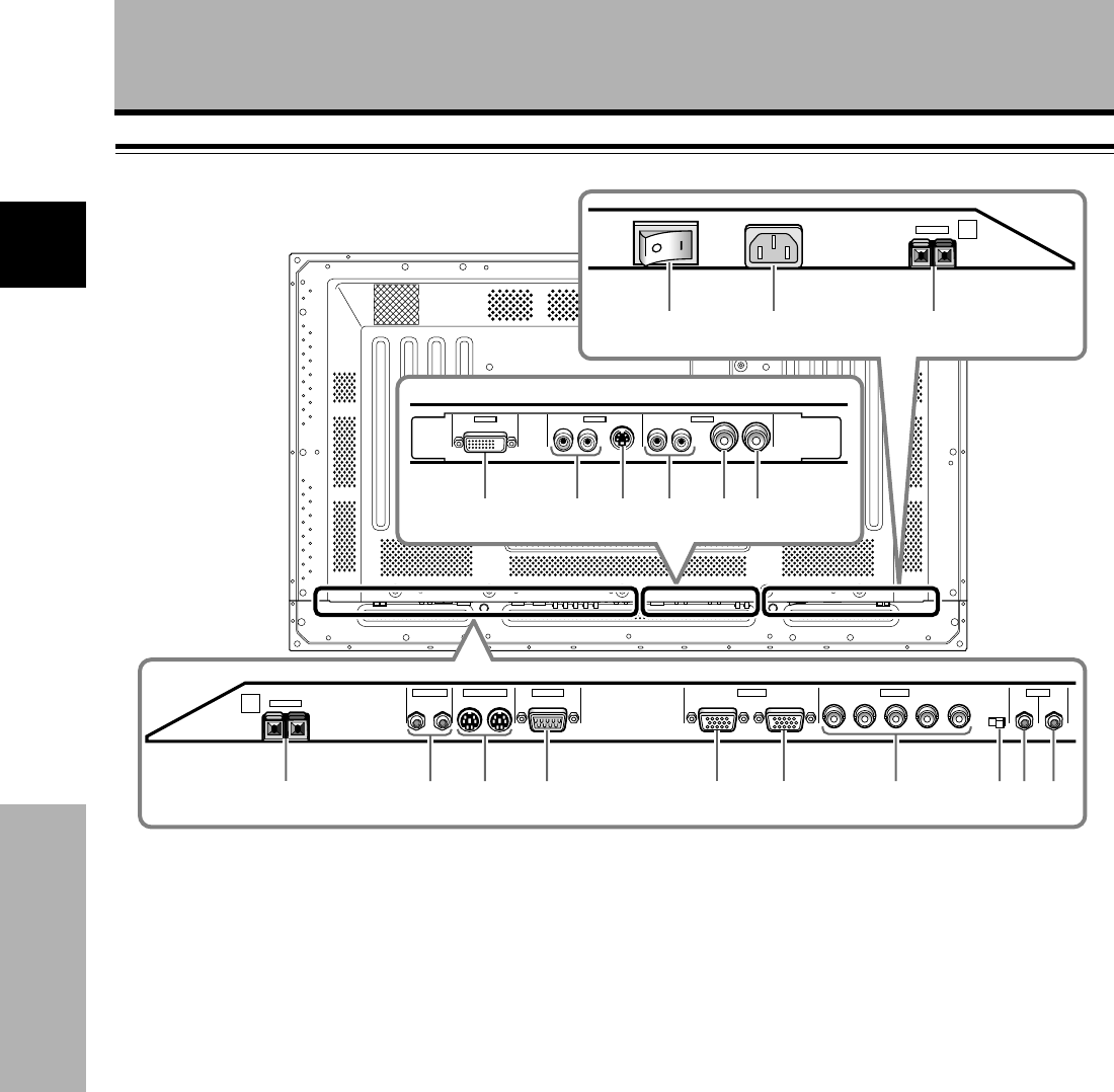
Plasma Display Section
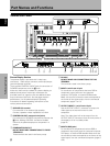
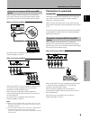
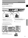
The plasma display is provided with 2 video input
connectors, 1 video output connector, audio input/output
jacks and speaker terminals.
There are also CONTROL IN/OUT jacks for connection of
PIONEER components with the Î mark.
When this video card is installed on a plasma display, an
additional three sets of video input connectors are
provided (total five), together with one additional video
output connector (total two). See the pages noted in
parentheses ( ) or the plasma display’s Operating
Instructions for details regarding connections to the
various jacks and connectors.
1 SPEAKER (R) terminal
For connection of an external right speaker.
Connect a speaker whose impedance is 8 -16 Ω.
2 CONTROL IN/OUT (monaural mini jacks)
For connection of PIONEER components that bear the
Î mark. Making CONTROL connection enables
control of the plasma display as a component in a
system.
3 COMBINATION IN/OUT
DO NOT MAKE ANY CONNECTIONS TO THESE
TERMINALS.
These terminals are used in the factory setup.
Connection Panel
4 RS-232C
DO NOT MAKE ANY CONNECTIONS TO THIS
TERMINAL.
This terminal is used in the factory setup.
5 INPUT1 (mini D-sub 15 pin)
For connection of components that have RGB or
component output jacks such as a personal
computer, DVD player, or external RGB decoder.
Make sure that the connection made corresponds to
the format of the signal output from the connected
component (pages 7 to 10).
6 OUTPUT (INPUT1) (mini D-sub 15 pin)
Use the OUTPUT (INPUT1) connector to output the
video signal to an external monitor or other
component.
Note: The video signal will not be output from the
OUTPUT (INPUT1) connector when the main power of
this display is off or in standby mode.
(page 10)
7 INPUT2 (BNC jacks)
For connection of components that have RGB or
component output jacks such as a personal computer,
DVD player, or external RGB decoder. Make sure that
the connection made corresponds to the format of the
signal output from the connected component (pages 7
to 9).
~=-
L
AC INLET
OFF ON
SPEAKER
8Ω ~16Ω
+ —
@! # $ % ^
AUDIO
INPUT5
INPUT3
S-VIDEO
RL
DIGITAL RGB
AUDIO
INPUT4
VIDEO OUTPUT
RL
1234 5 678
9
0
IN OUT
CONTROL
COMBINATION
IN OUT
RS-232C
ANALOG RGB (ANALOG RGB)
INPUT1
OUTPUT
GBRHDVD
(ON SYNC) (H/V SYNC)
Ô
75 2.2
Ω kΩ
INPUT
(INPUT1/2)
OUTPUT
R
SPEAKER
8Ω ~16Ω
+ —
INPUT2 AUDIO


