


INSTALLATION
EATON Powerware
®
9125 Two-in-One UPS (2500/3000 VA) User’s Guide S 164201374 Rev D
www.powerware.com
29
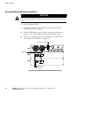
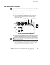
5. Insert each conduit through a wiring access entry and attach the
conduit fitting to the panel. Strip 1.5 cm (0.5I) of insulation from the
end of each incoming wire.
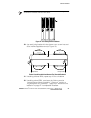
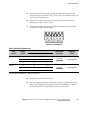
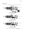
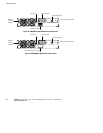
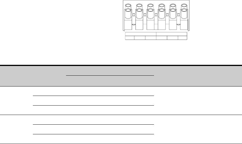
6. Connect the input and ground wires to the input terminal block
according to Figure 22 and Table 1.
7. Connect the output and ground wires to the output terminal block
according to Figure 22 and Table 1.
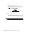
INPUT
13
OUTPUT
2465
Figure 22. Terminal Block
Table 1. UPS Wiring Specifications
W
i
r
e
T
e
r
m
i
n
a
l
UPS Wire Function
T
e
r
m
i
n
a
l
W
i
r
e
T
i
g
h
t
e
n
i
n
g
W
i
r
e
Function
T
e
r
m
i
n
a
l
Position
EUH Models EH and GH Models
T
e
r
m
i
n
a
l
W
i
r
e
Size Rating*
T
i
g
h
t
e
n
i
n
g
Torque
Input
1 L2 N
p
2 G G
2–10 mm
2
(
1
4
–
8
A
W
G
)
4.38 Nm (35 lb in)
3
L1 L
(
1
4
–
8
A
W
G
)
4
.
3
8
N
m
(
3
5
l
b
i
n
)
Output
4 L2 N
p
5 G G
2–10 mm
2
(
1
4
–
8
A
W
G
)
4.38 Nm (35 lb in)
6
L1 L
(
1
4
–
8
A
W
G
)
4
.
3
8
N
m
(
3
5
l
b
i
n
)
* Use 2.0 mm
2
(14 AWG) 75_C copper wire minimum.
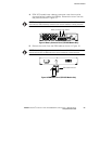
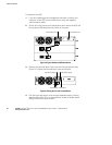
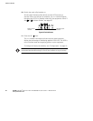
8. Reinstall the terminal block cover.
9. If an emergency power-off (disconnect) switch is required by local
codes, see “Remote Emergency Power-off Installation” on page 31
to install the REPO switch before powering on the UPS.