


ADDITIONAL UPS FEATURES
EATON Powerware
®
9125 Two-in-One UPS (2500/3000 VA) User’s Guide S 164201374 Rev D
www.powerware.com
47
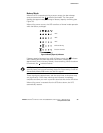
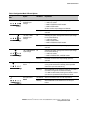
Table 3. Communication Port Pin Assignment
Pin Number Signal Name Function Direction from the UPS
1 Low Batt Low Battery relay contact; 20 mA, 30 Vdc contact rating Out
2 TxD Transmit to external device Out
3 RxD Receive from external device In
4 DTR PnP (Plug and Play) from external device (tied to Pin 6) In
5 GND Signal common (tied to chassis) —
6 DSR To external device (tied to Pin 4) Out
7 RTS PnP from external device (default) or On Bypass relay
contact (jumper-selectable)
In / Out
8 AC Fail AC Fail relay contact; 20 mA, 30 Vdc contact rating Out
9 Power Source +V (8 to 24 volts DC power) Out
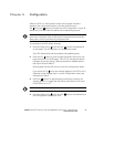
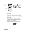
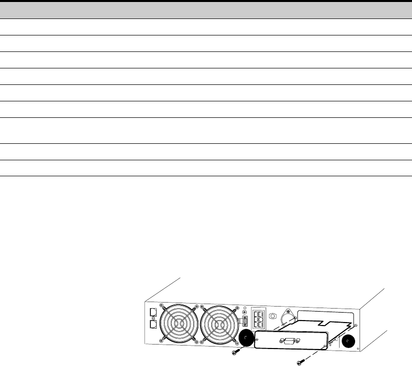
The On-Bypass Relay Contact. You can enable the On-Bypass relay using
the jumper on the Single-Port Card. The jumper default is disabled.
To enable the On-Bypass relay:
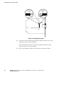
1. Remove the Single-Port Card on the UPS rear panel. Retain the
screws (see Figure 36).
Figure 36. Removing the Single-Port Card
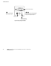
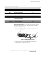
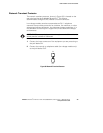
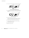
2. Move the J3 jumper to the AS/400
®
position to enable the
On-Bypass relay, as shown in Figure 37.