


INSTALLATION
EATON Powerware
®
9125 Two-in-One UPS (5000/6000 VA) User’s Guide S 164201513 Rev B
www.powerware.com
21
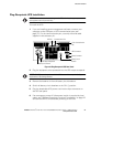
Plug-Receptacle UPS Installation
NOTE Do not make unauthorized changes to the UPS; o therwise, damage may occur to
your equipment and void your warranty.
To install the UPS:
1. If you are installing power management software, connect your
computer to the USB port or UPS communication port (see
page 37). For the communication port, use only the serial cable
supplied in the accessory kit.
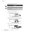
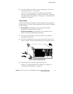
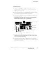
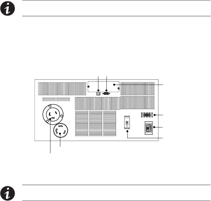
Battery Connector
Communication Port
L6-30 Input Connector
Battery Circuit
Breaker
REPO Connector
USB Port
X-Slot Communication
Bay
L6-30 Output Receptacle
Figure 10. Plug-Receptacle UPS Rear Panel
2. Plug the equipment to be protected into the UPS output receptacle.
NOTE DO NOT protect laser printers with the UPS because of the exceptionally high power
requirements of the heating elements.
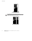
3. Remove the breaker tie from all battery circuit breakers.
4. Switch all battery circuit breakers to the ON (
| ) position.
5. Plug the detachable UPS power cord into the input connector on
the UPS rear panel.
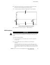
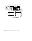
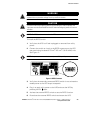
6. If an emergency power-off (disconnect) switch is required by local
codes, see “Remote Emergency Power-off Installation” on page 22
to install the REPO switch before powering on the UPS.