


COMMUNICATION
EATON Powerware
®
9125 Two-in-One UPS (5000/6000 VA) User’s Guide S 164201513 Rev B
www.powerware.com
38
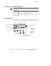
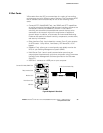
DB-9 Communication Port
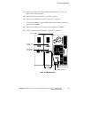
To establish communication between the UPS and a computer, connect
your computer to the UPS communication port using the supplied
communication cable (see Figure 18).
When the communication cable is installed, power management
software can exchange data with the UPS. The software polls the UPS
for detailed information on the status of the power environment. If a
power emergency occurs, the software initiates the saving of all data
and an orderly shutdown of the equipment.
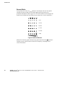
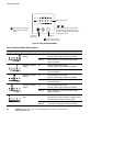
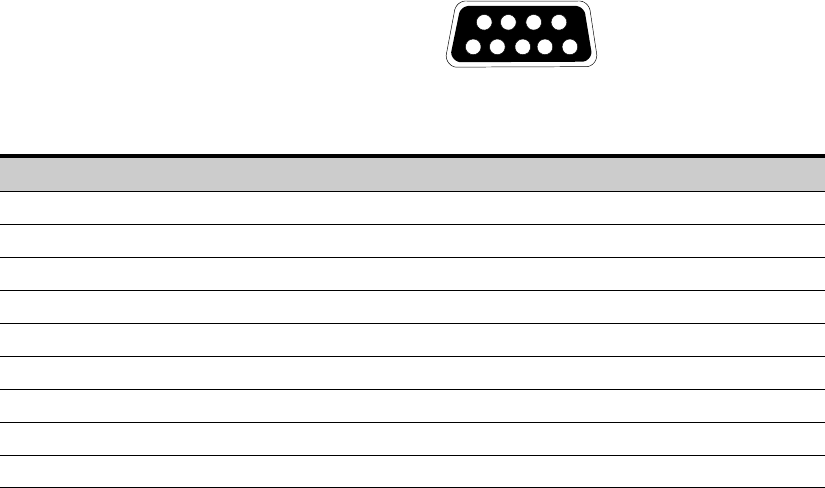
The cable pins are identified in Figure 19 and the pin functions are
described in Table 3.
3
8
7
9
1
6
245
Figure 19. Communication Port
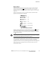
Table 3. Communication Port Pin Assignment
Pin Number Signal Name Function Direction from the UPS
1 Low Batt Low Battery relay contact; 20 mA, 30 Vdc contact rating Out
2 TxD Transmit to external device Out
3 RxD Receive from external device In
4 DTR PnP (Plug and Play) from external device (tied to Pin 6) In
5 GND Signal common (tied to chassis) —
6 DSR To external device (tied to Pin 4) Out
7 — No Connection —
8 AC Fail AC Fail relay contact; 20 mA, 30 Vdc contact rating Out
9 Power Source +V (8 to 24 volts DC power) Out