


INSTALLATION
EATON Powerware
®
9125 Two-in-One UPS (5000/6000 VA) User’s Guide S 164201513 Rev B
www.powerware.com
23
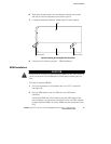
WARNING
The REPO circuit is an IEC 60950 safety extra low voltage (SELV) circuit. This circuit must be
separated from any hazardous voltage circuits by reinforced insulation.
CAUTION
To ensure the UPS stops supplying power to the load during any mode of operation, the
input power must be disconnected from the UPS when the emergency power-off function is
activated.
NOTE The REPO function activates when the REPO contacts close.
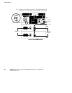
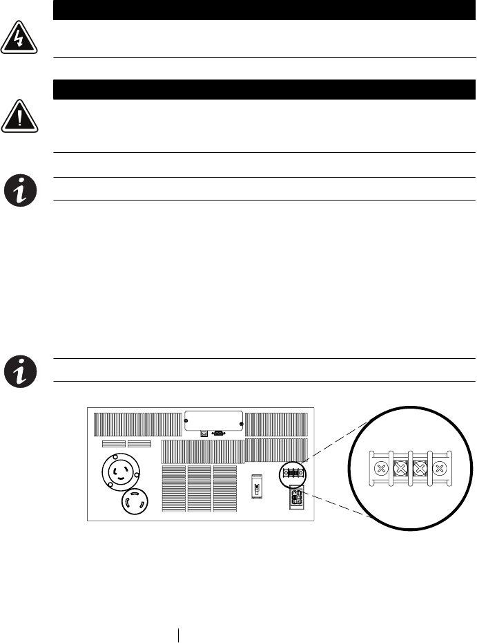
To install the REPO switch:
1. Verify that the UPS is off and unplugged or removed from utility
power.
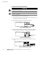
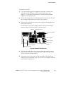
2. Connect the switch or circuit to the REPO connector on the UPS
rear panel using insulated 0.75 mm
2
–0.5 mm
2
(18–20 AWG) wire.
See Figure 11.
NOTE A separate contact must simultaneously cause UPS input AC power to be removed.
Figure 11. REPO Connector
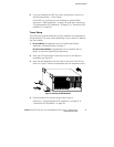
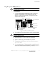
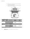
3. Verify that the externally-connected REPO switch is not activated to
enable power to the UPS output receptacle.
4. Plug in or apply utility power to the UPS and start the UPS by
pressing the On
button.
5. Activate the external REPO switch to test the REPO function.
6. De-activate the external REPO switch and restart the UPS.