


UNDERSTANDING UPS OPERATION
EATON Powerware
®
9395 UPS (650–825 kVA) Installation and Operation Manual S 164201725 Rev 2 www.powerware.com
6−13
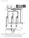
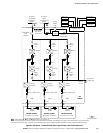
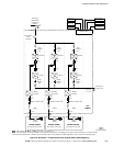
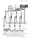
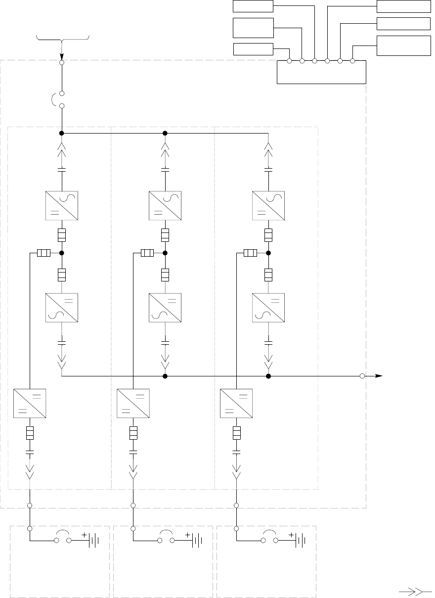
Input Breaker
(CB1)
(optional)
X−Slot
Interface
E1, E2, E3
48V Battery
Shunt Trip
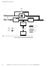
NOTE Callout letters A, B, C, and D map to Table 3-5 on page 3−10.
NOTE If the load requires a neutral, a bypass source neutral must be provided. If the load does not require a neutral and there is no neutral conductor
connected at the bypass input, a neutral to ground bonding jumper must be installed. DO NOT install both a source neutral and a bonding jumper.
UPS
CABINET
AC Output to
Critical Load
E9, E10,
E11, E12
AC Input to
UPS Rectifier
3 Wire A−B−C
Rotation
Interface Board
Battery Aux
Remote EPO
Building Alarms
Alarm Relays
Service Connector
Battery
Converter
Inverter
Output
Contactor
(K3)
Fuse
Rectifier
Input
Contactor
(K1)
Battery Contactor (K2)
Fuse
Fuse
Fuse
UPM 2
Battery
Breaker
E4. E5
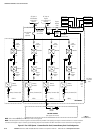
Battery
Converter
Inverter
Output
Contactor
(K3)
Fuse
Rectifier
Input
Contactor
(K1)
Battery Contactor (K2)
Fuse
Fuse
Fuse
UPM 3
Battery
Breaker
E4. E5
Battery
Breaker
E4. E5
Battery
Converter
Inverter
Output
Contactor
(K3)
Fuse
Rectifier
Input
Contactor
(K1)
Battery Contactor (K2)
Fuse
Fuse
Fuse
UPM 1
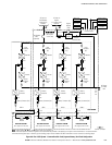
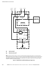
A
C
D
CC
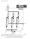
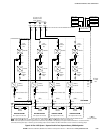
BATTERY SYSTEM
(Not supplied with the UPS)
BATTERY SYSTEM
(Not supplied with the UPS)
BATTERY SYSTEM
(Not supplied with the UPS)
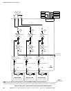
Figure 6-10. UPS System – Common Rectifier Feed, Separate Battery, IOM Configuration