


UPS INSTALLATION PLAN AND UNPACKING
EATON Powerware
®
9395 UPS (650–825 kVA) Installation and Operation Manual S 164201725 Rev 2 www.powerware.com
3−12
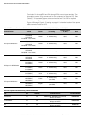
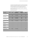
Terminals E1A through E5A and E9A through E12A are stud type terminals. The
intercabinet power wiring connections for this equipment are rated at 90°C. See
Table 3-7 for intercabinet power cable terminations and Table 3-8 for supplied
intercabinet wiring terminal hardware.
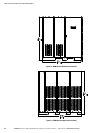
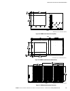
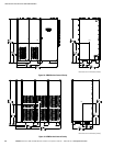
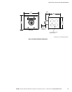
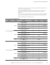
Figure 4-8 through Figure 4-13 starting on page 4−11 show the location of the power
cable terminals inside the UPS.
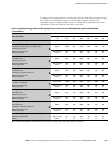
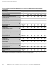
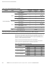
Table 3-7. UPS Intercabinet Power Cable Terminations for the Powerware 9395−825/650, 9395−825/750, and 9395−825/825
Terminal Function Terminal Function Bus Landing
Tightening Torque
Nm (lb ft)
Stud
AC Input to UPM Section
E1A (UPM 1)
E1A (UPM 2)
E1A (UPM 3)
E1A (UPM 4 – Plus 1 Model)
Phase A 3 – stud mounting 12 (8.3) M8
E2A (UPM 1)
E2A (UPM 2)
E2A (UPM 3)
E2A (UPM 4 – Plus 1 Model)
Phase B 3 – stud mounting 12 (8.3) M8
E3A (UPM 1)
E3A (UPM 2)
E3A (UPM 3)
E3A (UPM 4 – Plus 1 Model)
Phase C 3 – stud mounting 12 (8.3) M8
AC Output from UPM Section
E9A (UPM 1)
E9A (UPM 2)
E9A (UPM 3)
Phase A 3 – stud mounting 12 (8.3) M8
E10A (UPM 1)
E10A (UPM 2)
E10A (UPM 3)
Phase B 3 – stud mounting 12 (8.3) M8
E11A (UPM 1)
E11A (UPM 2)
E11A (UPM 3)
Phase C 3 – stud mounting 12 (8.3) M8
E12A (UPM 1)
E12A (UPM 2)
E12A (UPM 3)
Neutral 3 – stud mounting 12 (8.3) M8
DC Input to UPM Section
1E4A (UPM 1)
2E4A (UPM 2)
3E4A (UPM 3)
Positive
6 – stud mounting
(2 per UPM)
12 (8.3) M8
1E5A (UPM 1)
2E5A (UPM 2)
3E5A (UPM 3)
Negative
6 – stud mounting
(2 per UPM)
12 (8.3) M8
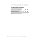
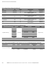
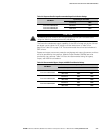
Table 3-8. Supplied Intercabinet Wiring Terminal Hardware Kit
Part Size Quantity Terminals Used On Eaton Part Number
Flat Washer M8 36
UPM AC Input, UPM Battery Input, UPM AC
Output, and Neutral
180500036−080
Conical Washer M8 36
UPM AC Input, UPM Battery Input, UPM AC
Output, and Neutral
180500037−080
Nut M8 36
UPM AC Input, UPM Battery Input, UPM AC
Output, and Neutral
180200001−05