


UPS INSTALLATION PLAN AND UNPACKING
EATON Powerware
®
9395 UPS (650–825 kVA) Installation and Operation Manual S 164201725 Rev 2 www.powerware.com
3−17
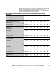
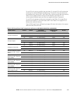
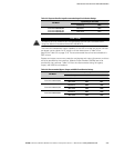
Table 3-15. Separate Rectifier Input Recommended Input Circuit Breaker Ratings
UPS Model
Input Rating for Each UPM
Load Rating 480V
Powerware 9395−825/650
Powerware 9395−825/750
Powerware 9395−825/825
80% Rated 500A
100% Rated 400A
C A U T I O N
To reduce the risk of fire, connect only to a circuit provided with maximum input circuit breaker current
ratings from Table 3-14 in accordance with the NEC, ANSI/NFPA 70.
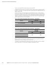
The line-to-line unbalanced output capability of the UPS is limited only by the full load
per phase current values for AC output to critical load shown in Table 3-4 on
page 3−9 or Table 3-5 on page 3−10. The recommended line-to-line load unbalance is
50% or less.
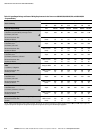
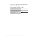
Bypass and output overcurrent protection and bypass and output disconnect switches
are to be provided by the customer. Module Output Breakers (MOBs) are to be
provided by the customer. Table 3-16 lists the recommended rating for bypass,
output, and MOB circuit breakers.
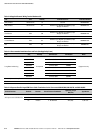
Table 3-16. Recommended Bypass, Output, and MOB Circuit Breaker Ratings
UPS Model
Output Rating
Load Rating 400V 480V
Powerware 9395−825/650
80% Rated 1200A 1000A
100% Rated 1000A 800A
Powerware 9395−825/750
80% Rated 1600A 1200A
100% Rated 1200A 1000A
Powerware 9395−825/825
80% Rated 1600A 1600A
100% Rated 1200A 1000A