


TABLE OF CONTENTS
EATON Powerware
®
9395 UPS (650–825 kVA) Installation and Operation Manual S 164201725 Rev 2 www.powerware.com
v
List of Figures
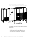
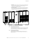
Figure 1-1. Powerware 9395 UPS (650–825 kVA) 1−2. . . . . . . . . . . . . . . . . . . . . . . . . . . . . . . . . . . . . . . . . . . . . . . . . . . . . . . . . . . . . .
Figure 1-2. Powerware 9395 UPS (650–825 kVA) with the Field Installed UPM 1−3. . . . . . . . . . . . . . . . . . . . . . . . . . . . . . . . . . . . . . . . .
Figure 3-1. UPS Cabinet Dimensions (Front View) 3−3. . . . . . . . . . . . . . . . . . . . . . . . . . . . . . . . . . . . . . . . . . . . . . . . . . . . . . . . . . . . .
Figure 3-2. UPS Cabinet Dimensions (Right Side View) 3−3. . . . . . . . . . . . . . . . . . . . . . . . . . . . . . . . . . . . . . . . . . . . . . . . . . . . . . . . . .
Figure 3-3. ISBM Section Dimensions (Front View) 3−4. . . . . . . . . . . . . . . . . . . . . . . . . . . . . . . . . . . . . . . . . . . . . . . . . . . . . . . . . . . . .
Figure 3-4. UPM Section Dimensions (Front View) 3−4. . . . . . . . . . . . . . . . . . . . . . . . . . . . . . . . . . . . . . . . . . . . . . . . . . . . . . . . . . . . .
Figure 3-5. ISBM Section Dimensions (Top View) 3−5. . . . . . . . . . . . . . . . . . . . . . . . . . . . . . . . . . . . . . . . . . . . . . . . . . . . . . . . . . . . . .
Figure 3-6. ISBM Section Dimensions (Bottom View) 3−5. . . . . . . . . . . . . . . . . . . . . . . . . . . . . . . . . . . . . . . . . . . . . . . . . . . . . . . . . . .
Figure 3-7. UPM Section Dimensions (Top View) 3−5. . . . . . . . . . . . . . . . . . . . . . . . . . . . . . . . . . . . . . . . . . . . . . . . . . . . . . . . . . . . . .
Figure 3-8. ISBM Section Center of Gravity 3−6. . . . . . . . . . . . . . . . . . . . . . . . . . . . . . . . . . . . . . . . . . . . . . . . . . . . . . . . . . . . . . . . . .
Figure 3-9. UPM Section Center of Gravity 3−6. . . . . . . . . . . . . . . . . . . . . . . . . . . . . . . . . . . . . . . . . . . . . . . . . . . . . . . . . . . . . . . . . .
Figure 3-10. Remote EPO Switch Dimensions 3−7. . . . . . . . . . . . . . . . . . . . . . . . . . . . . . . . . . . . . . . . . . . . . . . . . . . . . . . . . . . . . . . .
Figure 3-11. UPS Cabinet as Shipped on Pallet (ISBM Section) 3−22. . . . . . . . . . . . . . . . . . . . . . . . . . . . . . . . . . . . . . . . . . . . . . . . . . . .
Figure 3-12. UPS Cabinet as Shipped on Pallet (UPM Section) 3−23. . . . . . . . . . . . . . . . . . . . . . . . . . . . . . . . . . . . . . . . . . . . . . . . . . . . .
Figure 4-1. Removing the ISBM Section Left Side Shipping Bracket 4−2. . . . . . . . . . . . . . . . . . . . . . . . . . . . . . . . . . . . . . . . . . . . . . . . .
Figure 4-2. Removing the ISBM Section Right Side Shipping Bracket 4−3. . . . . . . . . . . . . . . . . . . . . . . . . . . . . . . . . . . . . . . . . . . . . . . .
Figure 4-3. Removing the UPM Section Left Side Shipping Bracket 4−4. . . . . . . . . . . . . . . . . . . . . . . . . . . . . . . . . . . . . . . . . . . . . . . . .
Figure 4-4. Removing the UPM Section Right Side Shipping Bracket 4−5. . . . . . . . . . . . . . . . . . . . . . . . . . . . . . . . . . . . . . . . . . . . . . . .
Figure 4-5. Section Joining 4−6. . . . . . . . . . . . . . . . . . . . . . . . . . . . . . . . . . . . . . . . . . . . . . . . . . . . . . . . . . . . . . . . . . . . . . . . . . . . .
Figure 4-6. ISBM and UPM Sections Joined 4−7. . . . . . . . . . . . . . . . . . . . . . . . . . . . . . . . . . . . . . . . . . . . . . . . . . . . . . . . . . . . . . . . .
Figure 4-7. ISBM Section to UPM Section Joining Brackets 4−8. . . . . . . . . . . . . . . . . . . . . . . . . . . . . . . . . . . . . . . . . . . . . . . . . . . . . .
Figure 4-8. ISBM Section Intercabinet Power Terminal Locations – Common Rectifier Feed 4−11. . . . . . . . . . . . . . . . . . . . . . . . . . . . . . . .
Figure 4-9. ISBM Section Input Power Terminal Detail – Common Rectifier Feed 4−12. . . . . . . . . . . . . . . . . . . . . . . . . . . . . . . . . . . . . . . .
Figure 4-10. ISBM Section Intercabinet Power Terminal Locations – Separate Rectifier Feed 4−13. . . . . . . . . . . . . . . . . . . . . . . . . . . . . . .
Figure 4-11. ISBM Section Input Power Terminal Detail – Separate Rectifier Feed 4−14. . . . . . . . . . . . . . . . . . . . . . . . . . . . . . . . . . . . . .
Figure 4-12. ISBM Section Battery Input Power Terminal Detail 4−15. . . . . . . . . . . . . . . . . . . . . . . . . . . . . . . . . . . . . . . . . . . . . . . . . . .
Figure 4-13. ISBM Section Output Power Terminal Detail 4−15. . . . . . . . . . . . . . . . . . . . . . . . . . . . . . . . . . . . . . . . . . . . . . . . . . . . . . . .
Figure 4-14. UPS Intercabinet Interface Harness Locations 4−16. . . . . . . . . . . . . . . . . . . . . . . . . . . . . . . . . . . . . . . . . . . . . . . . . . . . . . .
Figure 4-15. Pl1 Interface Board Location 4−17. . . . . . . . . . . . . . . . . . . . . . . . . . . . . . . . . . . . . . . . . . . . . . . . . . . . . . . . . . . . . . . . . . .
Figure 4-16. J39 Location on Pl1 Interface Board 4−17. . . . . . . . . . . . . . . . . . . . . . . . . . . . . . . . . . . . . . . . . . . . . . . . . . . . . . . . . . . . . .
Figure 4-17. ISBM and UPM Section Debris Shields 4−19. . . . . . . . . . . . . . . . . . . . . . . . . . . . . . . . . . . . . . . . . . . . . . . . . . . . . . . . . . . .
Figure 4-18. ISBM Section Conduit and Wire Entry Locations 4−20. . . . . . . . . . . . . . . . . . . . . . . . . . . . . . . . . . . . . . . . . . . . . . . . . . . . .
Figure 4-19. Distributed Bypass Wire Length 4−22. . . . . . . . . . . . . . . . . . . . . . . . . . . . . . . . . . . . . . . . . . . . . . . . . . . . . . . . . . . . . . . . .
Figure 4-20. ISBM Section Power Terminal Locations – Common Rectifier Feed 4−23. . . . . . . . . . . . . . . . . . . . . . . . . . . . . . . . . . . . . . . .
Figure 4-21. ISBM Section Power Terminal Detail AA – Common Rectifier Feed 4−24. . . . . . . . . . . . . . . . . . . . . . . . . . . . . . . . . . . . . . . .
Figure 4-22. ISBM Section Power Terminal Locations – Separate Rectifier Feed 4−25. . . . . . . . . . . . . . . . . . . . . . . . . . . . . . . . . . . . . . . .
Figure 4-23. ISBM Section Power Terminal Detail AA – Separate Rectifier Feed 4−26. . . . . . . . . . . . . . . . . . . . . . . . . . . . . . . . . . . . . . . .
Figure 4-24. UPM Rectifier Input Power Terminal Block Detail 4−27. . . . . . . . . . . . . . . . . . . . . . . . . . . . . . . . . . . . . . . . . . . . . . . . . . . . .
Figure 4-25. ISBM Section Power Terminal Detail BB – Common Battery 4−29. . . . . . . . . . . . . . . . . . . . . . . . . . . . . . . . . . . . . . . . . . . . .
Figure 4-26. ISBM Section Power Terminal Detail CC – Separate Battery 4−30. . . . . . . . . . . . . . . . . . . . . . . . . . . . . . . . . . . . . . . . . . . . .
Figure 4-27. ISBM Section Interface Terminal Locations 4−32. . . . . . . . . . . . . . . . . . . . . . . . . . . . . . . . . . . . . . . . . . . . . . . . . . . . . . . . .
Figure 4-28. Interface Terminal Detail 4−34. . . . . . . . . . . . . . . . . . . . . . . . . . . . . . . . . . . . . . . . . . . . . . . . . . . . . . . . . . . . . . . . . . . . .
Figure 4-29. Typical Alarm Relay Connection 4−34. . . . . . . . . . . . . . . . . . . . . . . . . . . . . . . . . . . . . . . . . . . . . . . . . . . . . . . . . . . . . . . . .
Figure 4-30. Terminal Blocks TB1, TB2, and TB3 Connector Assignments 4−35. . . . . . . . . . . . . . . . . . . . . . . . . . . . . . . . . . . . . . . . . . . . .
Figure 4-31. Typical Battery Interface Connection – Common Battery System 4−37. . . . . . . . . . . . . . . . . . . . . . . . . . . . . . . . . . . . . . . . . .
Figure 4-32. Typical Battery Interface Connection – Separate Battery System 4−37. . . . . . . . . . . . . . . . . . . . . . . . . . . . . . . . . . . . . . . . . .
Figure 4-33. X−Slot Communication Bays 4−38. . . . . . . . . . . . . . . . . . . . . . . . . . . . . . . . . . . . . . . . . . . . . . . . . . . . . . . . . . . . . . . . . . .