


UPS SYSTEM INSTALLATION
EATON Powerware
®
9395 UPS (650–825 kVA) Installation and Operation Manual S 164201725 Rev 2 www.powerware.com
4−38
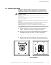
4.9.3 X−Slot Connections
NOTE LAN and telephone drops for use with X−Slot cards must be provided by the customer.
NOTE When installing external wiring to X−Slot cards, conduit must be installed to the UPS cabinet. When
installing internal wiring to X−Slot terminals, route the wiring through the internal opening in the X−Slot
communication bay.
For installation and setup of an X−Slot card, contact an Eaton service representative
(see page 1−8).
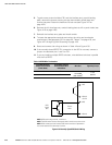
To install wiring to connections:
1. If not already installed, install the LAN and telephone drops.
2. Unfasten the front door latch and swing the door open (see Figure 4-1 on
page 4−2).
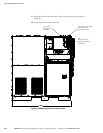
3. Remove the right interface entry conduit landing plate to drill or punch holes (see
Figure 4-18 on page 4−20).
4. Reinstall the interface entry plate and install the conduit.
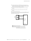
5. Route and install the LAN, telephone, and other cables to the appropriate X−Slot
cards. See Figure 4-27 on page 4−32 and Figure 4-33 for X−Slot communication
bay locations.
6. Close the door and secure the latch.
7. Refer to the manual supplied with the X−Slot card for operator instructions.
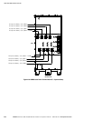
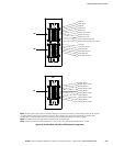
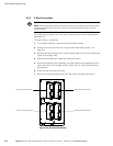
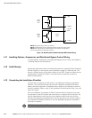
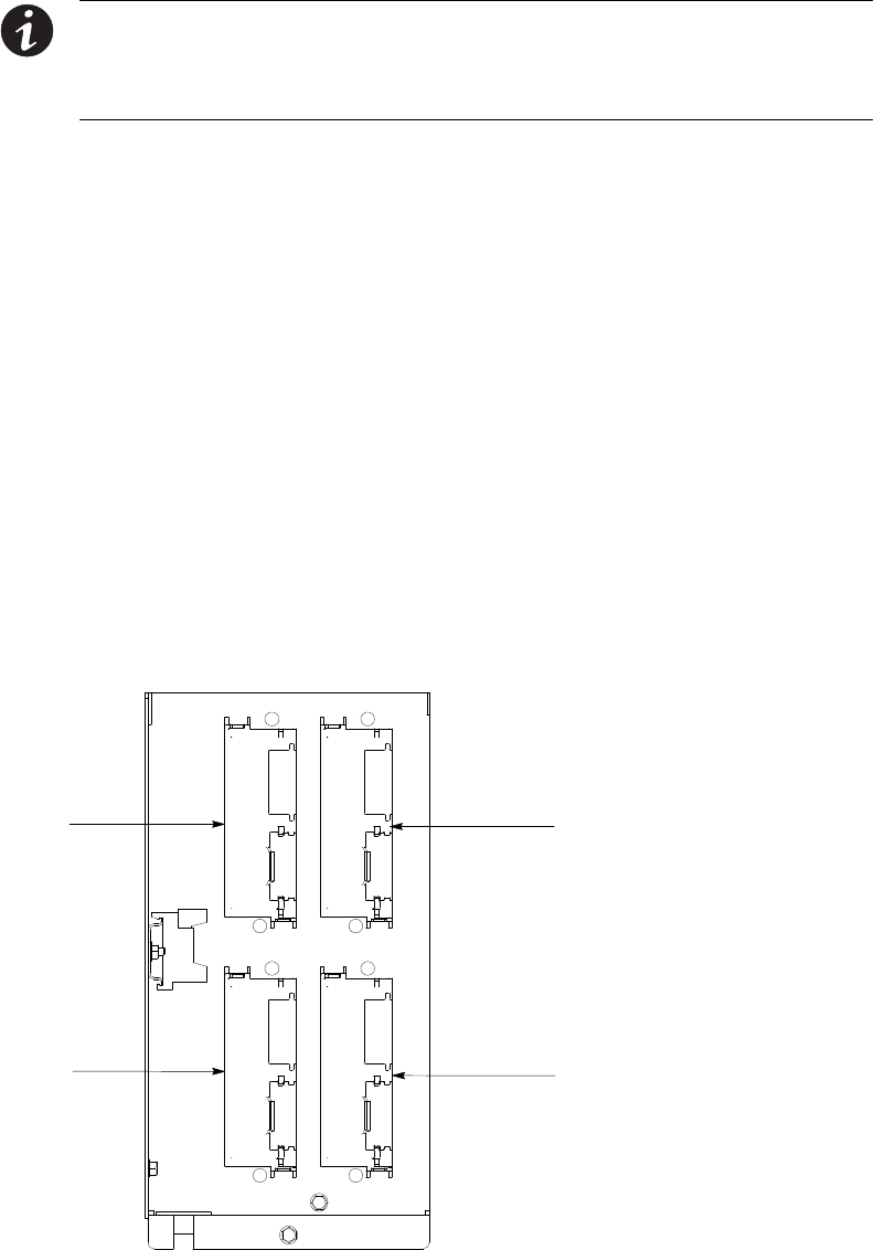
X−Slot Communication Bay 1
X−Slot Communication Bay 2
X−Slot Communication Bay 3
X−Slot Communication Bay 4
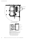
Figure 4-33. X−Slot Communication Bays