


UPS INSTALLATION PLAN AND UNPACKING
EATON Powerware
®
9395 UPS (650–825 kVA) Installation and Operation Manual S 164201725 Rev 2 www.powerware.com
3−19
3.2.3 UPS System Interface Wiring Preparation
Control wiring for features and options should be connected at the customer interface
terminal blocks located inside the UPS.
W A R N I N G
Do not directly connect relay contacts to the mains related circuits. Reinforced insulation to the mains is
required.
Read and understand the following notes while planning and performing the
installation:
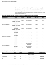
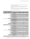
S Use Class 1 wiring methods (as defined by the NEC) for interface wiring up to 30V.
The wire should be rated at 24V, 1A minimum.
S Use Class 2 wiring methods (as defined by the NEC) for interface wiring from 30V
to 600V. The wire should be rated at 600V, 1A minimum and 12 AWG maximum.
S Use twisted-pair wires for each input and return or common.
S All interface wiring and conduit is to be provided by the customer.
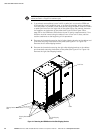
S When installing external interface wiring (for example, building alarm, relay output,
battery breaker trip, and X−Slot) to the UPS interface terminals, conduit must be
installed between each device and the UPS cabinet.
S Install the interface wiring in separate conduit from the power wiring.
S When installing internal interface wiring to X−Slot terminals, route the wiring
through the internal opening in the X−Slot communication bay.
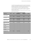
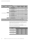
S All building alarm inputs or remote features require an isolated normally-open
contact or switch (rated at 24 Vdc, 20 mA minimum) connected between the alarm
input and common terminal. All control wiring and relay and switch contacts are
customer-supplied.
S The building alarms can be programmed to display the alarm functional name.
S LAN and telephone drops for use with X−Slot connectivity cards must be provided
by the customer.
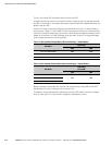
S The UPS battery aux signal wiring from the UPS must be connected to the battery
disconnect device.
S A supplemental 48 Vdc shunt trip signal for the battery disconnect device is
provided, but is not required for normal operation.
S Battery aux and 48 Vdc shunt trip wiring should be a minimum of 18 AWG.
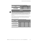
S The REPO feature opens all contactors in the UPS cabinet and isolates power from
your critical load. Local electrical codes may also require tripping upstream
protective devices to the UPS.
S The REPO switch must be a latching−type switch not tied to any other circuits.
S A jumper wire must be connected between pins 1 and 2 on TB1, if the
normally-closed REPO contact is not used.
S REPO wiring should be a minimum of 22 AWG and a maximum of 14 AWG.