


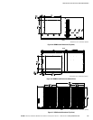

UPS INSTALLATION PLAN AND UNPACKING
EATON Powerware
®
9395 UPS (650–825 kVA) Installation and Operation Manual S 164201725 Rev 2 www.powerware.com
3−13
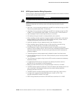
For an UPS with common rectifier input terminals, E1 through E12 are 2-hole bus bar
mountings for standard NEMA 2-hole barrel lugs. The power wiring connections for
this equipment are rated at 90°C. See Table 3-9 for external power cable terminations,
Table 3-10 for supplied external wiring terminal hardware, and Table 3-11 for
recommended installation parts and tools not supplied by Eaton Corporation.
For an UPS with separate rectifier input terminals for the UPMs, E1 through E3 are
pressure terminations, UL and CSA rated at 90°C. See Table 3-12 on page 3−14 for
these power cable terminations.
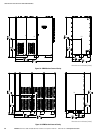
Figure 4-20 through Figure 4-26 starting on page 4−24 show the location of the power
cable terminals inside the UPS.
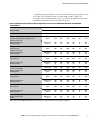
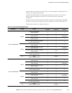
Table 3-9. UPS External Power Cable Terminations for the Powerware 9395−825/650, 9395−825/750, and 9395−825/825
Terminal Function Terminal Function
Bus Landings
(using both sides of bus)
Tightening Torque
Nm (lb ft)
Bolt Size
AC Input to UPS Rectifier
E1 Phase A 4 – 2 bolt mounting
76 (56)
M12
E2 Phase B 4 – 2 bolt mounting
76 (56)
M12
E3 Phase C 4 – 2 bolt mounting
76 (56)
M12
AC Input to Bypass
E6 Phase A 6 – 2 bolt mounting
76 (56)
M12
E7 Phase B 6 – 2 bolt mounting
76 (56)
M12
E8 Phase C 6 – 2 bolt mounting
76 (56)
M12
AC Output to Critical Load
E9 Phase A 6 – 2 bolt mounting
76 (56)
M12
E10 Phase B 6 – 2 bolt mounting
76 (56)
M12
E11 Phase C 6 – 2 bolt mounting
76 (56)
M12
DC Input from Battery or Battery
Disconnect to UPS – Common
Battery
E4 Battery (+) 12 – 2 bolt mounting
76 (56)
M12
E5 Battery (−) 12 – 2 bolt mounting
76 (56)
M12
DC Input from Battery or Battery
Disconnect to UPS – Separate
Battery (UPM 1)
E4 Battery (+) 4 – 2 bolt mounting
76 (56)
M12
E5 Battery (−) 4 – 2 bolt mounting
76 (56)
M12
DC Input from Battery or Battery
Disconnect to UPS – Separate
Battery (UPM 2)
E4 Battery (+) 4 – 2 bolt mounting
76 (56)
M12
E5 Battery (−) 4 – 2 bolt mounting
76 (56)
M12
DC Input from Battery or Battery
Disconnect to UPS – Separate
Battery (UPM 3)
E4 Battery (+) 4 – 2 bolt mounting
76 (56)
M12
E5 Battery (−) 4 – 2 bolt mounting
76 (56)
M12
DC Input from Battery or Battery
Disconnect to UPS – Separate
Battery (UPM 4 FI−UPM)
E4 Battery (+) 4 – 2 bolt mounting
76 (56)
M12
E5 Battery (−) 4 – 2 bolt mounting
76 (56)
M12
Input and Output Neutral E12 Neutral 12 – 2 bolt mounting 22 (16) M10
Customer Ground Ground Ground 15 – 1 bolt mounting 22 (16) M10
NOTE Customer ground, sized in accordance with NEC Table 250.122, can be run in any conduit listed in Table 3-13 on page 3−15.