


UNDERSTANDING UPS OPERATION
EATON Powerware
®
9395 UPS (650–825 kVA) Installation and Operation Manual S 164201725 Rev 2 www.powerware.com
6−15
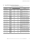
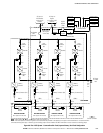
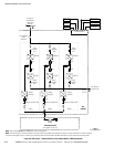
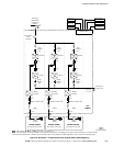
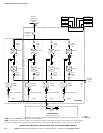
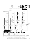
Input Breaker
(CB1)
(optional)
E1, E2, E3
NOTE Callout letters
A, B, C, and D map to Table 3-5 on page 3−10.
NOTE If the load requires a neutral, a bypass source neutral must be provided. If the load does not require a neutral and there is no neutral conductor
connected at the bypass input, a neutral to ground bonding jumper must be installed. DO NOT install both a source neutral and a bonding jumper.
UPS CABINET
E9,
E10,
E11,
E12
AC Input to
UPS Rectifier
3 Wire A−B−C
Rotation
Service Connector
Battery
Converter
Inverter
Output
Contactor
(K3)
Fuse
Rectifier
Input
Contactor
(K1)
Battery Contactor (K2)
Fuse
Fuse
Fuse
UPM 2
Battery
Breaker
E4. E5
Battery
Converter
Inverter
Output
Contactor
(K3)
Fuse
Rectifier
Input
Contactor
(K1)
Battery Contactor (K2)
Fuse
Fuse
Fuse
UPM 3
Battery
Breaker
E4. E5
Battery
Breaker
E4. E5
Battery
Converter
Inverter
Output
Contactor
(K3)
Fuse
Rectifier
Input
Contactor
(K1)
Battery Contactor (K2)
Fuse
Fuse
Fuse
UPM 1
Bypass
Breaker
(CB4)
Battery
Converter
Inverter
Output
Contactor
(K3)
Fuse
Rectifier
Input
Contactor
(K1)
Battery Contactor (K2)
Fuse
Fuse
Fuse
UPM 4
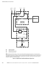
X−Slot
Interface
48V Battery
Shunt Trip
Interface Board
Battery Aux
Remote EPO
Building Alarms
Alarm Relays
FI−UPM CABINET
Battery
Breaker
A
C
D
CC
AC Output
to Critical
Load
C
BATTERY SYSTEM
(Not supplied with the UPS)
BATTERY SYSTEM
(Not supplied with the UPS)
BATTERY SYSTEM
(Not supplied with the UPS)
BATTERY SYSTEM
(Not supplied with the UPS)
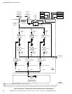
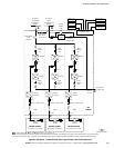
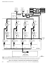
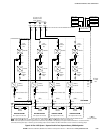
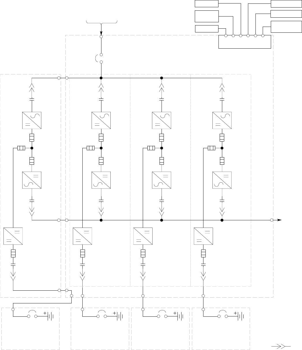
Figure 6-12. Plus 1 UPS System – Common Rectifier Feed, Separate Battery, IOM Configuration