


134 = Image Server 2000
Redundancy............................................101
Transfer Marked Segment ...........................98
Transfer Rate.............................................98
Networking...................................................98
Odetics
Serial Control ............................................71
Odetics® Protocol ........................................127
On-Screen
Configuration Menu...................................29
File Menu.................................................29
Main Menu...............................................28
Transport Menu.........................................29
Window Menu..........................................29
Operations....................................................27
Out Point Display .................................... 46, 69
Outputs
Audio.......................................................22
Video.......................................................22
P2
Command Table......................................125
Serial Control ............................................71
Phase
Color Framing ...........................................79
Sub-Carrier................................................87
Pinout
GPIO .....................................................121
Play Button ...................................................37
Playback
Concurrent................................................75
Playing
Clip..........................................................43
Playlists, Seamless .........................................75
Power Connector...........................................25
Power LED..................................................104
Power ON/OFF Button...................................20
Power Sources...............................................25
Program Updates
CD-ROM................................................111
Protocol........................................................71
Rack Mounting ..............................................18
Radio Interference Compliance .....................113
RAID
Card.......................................................107
Fault Tolerance..........................................89
Performance..............................................89
Repair ......................................................90
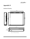
Rear Panel
Drawing ............................................. 21, 22
Features.............................................. 21, 22
Indicators................................................105
Reboot .........................................................27
Record
Button ......................................................32
Setup........................................................76
Record Button ...............................................36
Recording
New.........................................................32
Regulatory Compliance ................................113
Repair ........................................................112
Replacing a Hard Drive................................112
Restart..........................................................27
Review Clip Button.................................. 46, 69
Review Out Point Button.......................... 47, 69
Sample Rate Conversion.................................85
Save..................................................33, 34, 35
Save As.........................................................34
SC/H Phase ...................................................87
Schematic
GPIO .....................................................121
SDI ..................................9, 13, 22, 38, 85, 130
Serial Control Ports ........................................23
Serial Protocol
Command Table......................................123
P2 125
VDCP.....................................................123
Service
Access....................................................105
Front Panel .............................................105
Top Cover...............................................105
Shutdown............................................... 27, 91
Shuttle..........................................................38
Slider Bar......................................................38
Software License Agreement.........................117
Software Version .........................................111
Specifications
Connectors .............................................119
Technical................................................130
SRC..............................................................85
Still ...........................................See Stop Button
Still Frames...................................................55
Stop (Still) Button...........................................37
Storage Capacity..............................................9
Sub-Carrier Phase ..........................................87
SVGA Connector Pinout ...............................122
Symbols
Warning And Information.............................7
Sync Reference
Genlock ...................................................24
System
Timing Tab ...............................................78
System Board Ports ......................................122
System LED.................................................104
System Menu .......................................... 29, 76
TARGA File Ingest.........................................53
TARGA Files..........................................54, 100
Time
System................................................ 29, 77
Time Code