


Chapter 2 System Component Descriptions 19
19
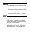
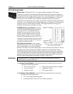
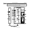
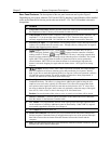
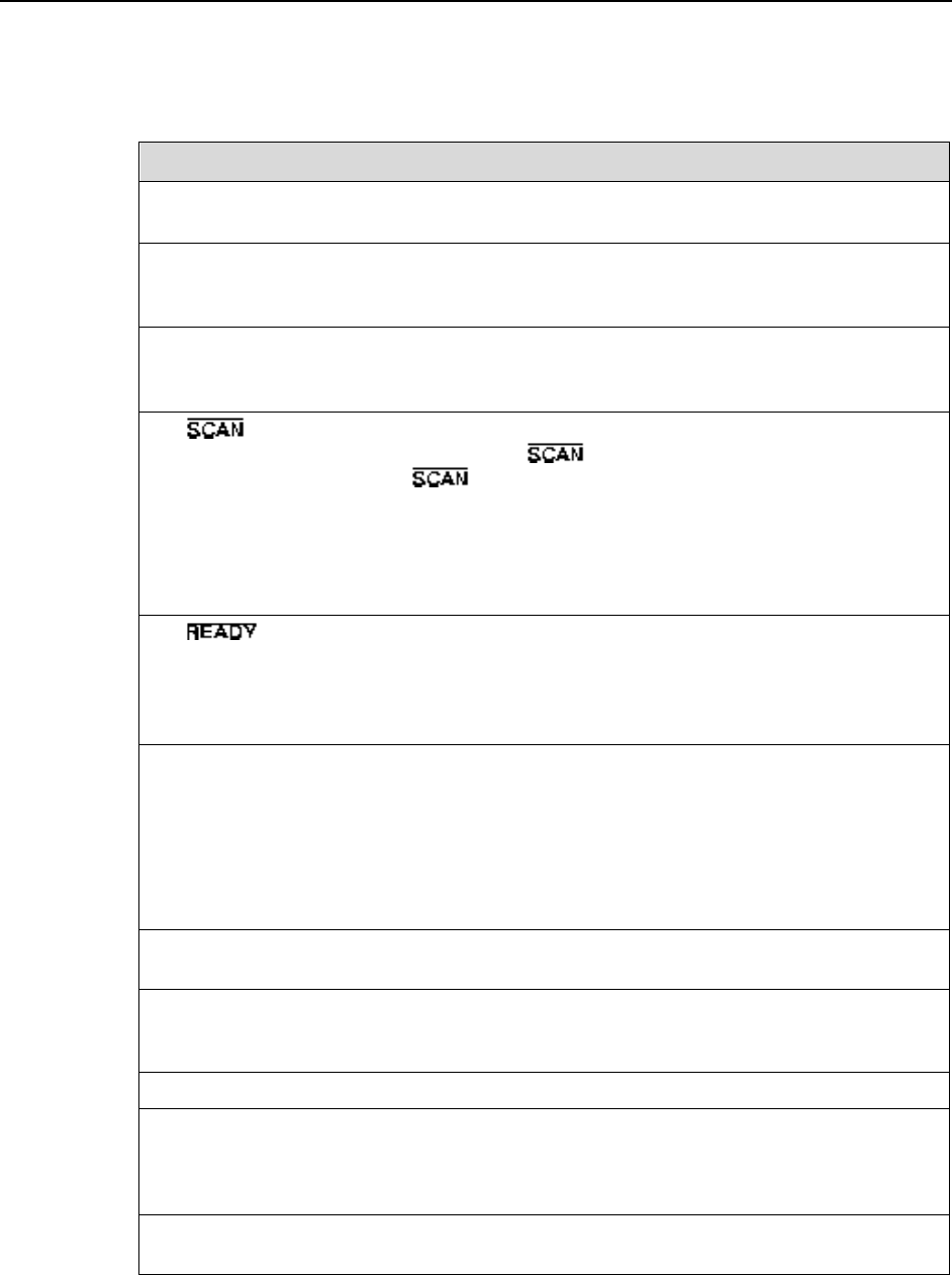
Rear Panel Features: The descriptions of the rear panel connectors are keyed to Figure 3.
Depending on your system, either the TAXI or the USB 2.0 Interface Control Module will be installed
in the second from the left slot (as you face the rear of the ST-133). The TAXI module is shown in
that position.
# Feature
1. Temperature Lock LED: Indicates that the temperature control loop has locked and that
the temperature of the CCD array will be stable to within 0.05C.
2. Video Output: If labeled Video, composite video output is provided at this connector. The
amplitude is 1 V pk-pk and the source impedance is 75 . Note that video output is not
currently supported under USB 2.0. If labeled Aux, this output is reserved for future use.
3. External Sync Input: TTL input that has a 10 k pullup resistor. Allows data acquisition and
readout to be synchronized with external events. Through software, either positive or negative
(default) edge triggering can be selected.
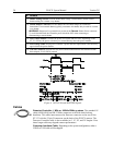
4. Output WinView/32 (ver. 2.4 and higher) software selectable NOT SCAN or
SHUTTER signal. Default is SHUTTER. , reports when the controller is finished
reading out the CCD array. is high when the CCD array is not being scanned, then
drops low when readout begins, returning to high when the process is finished. The second
signal, SHUTTER, reports when the shutter is opened and can be used to synchronize
external shutters. SHUTTER is low when the shutter is closed and goes high when the
shutter is activated, dropping low again after the shutter closes. See Figure 4 for timing
diagram.
5. Output: Initially HIGH. After a Start Acquisition command, this output changes
state on completion of the array cleaning cycles that precede the first exposure. Initially
high, it goes low to mark the beginning of the first exposure. In free run operation it remains
low until the system is halted. If a specific number of frames have been programmed, it
remains low until all have been taken, then returns high.
6. Zero Adjustment: Control the offset values of the Fast (F) and Slow (S) A/D converters.
Preadjusted at factory. The offset is a voltage that is added to the signal to bring the A/D
output to a non-zero value, typically 50-100 counts. This offset value ensures that all the
true variation in the signal can really be seen and not lost below the A/D "0" value. Since
the offset is added to the signal, these counts only minimally reduce the range of the signal
from 65535 (16-bit A/D) to a value in the range of 50-100 counts lower.
Caution: Do not adjust the offset values to zero, or some low-level data will be missed.
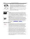
7. Detector Connector: Transmits control information to the camera and receives data back
from the camera via the Detector-Controller cable.
8. TTL In/Out: User-programmable interface with eight input bits and eight output bits that
can be written to or polled for additional control or functionality. Under USB 2.0, output is
not currently supported in WinView. See Chapter 6.
9. AUX Output: Reserved for future use.
10. Serial COM Connector: Provides two-way serial communication between the controller and
the host computer. Contact the factory if an application requires use of the optional fiberoptic
data link to increase the maximum allowable distance between the Camera and the
computer.
11. Fan: Cools the controller electronics. Runs continuously when the controller is turned on. Do not
block the side vents or the fan exhaust port.