


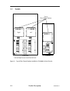
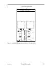
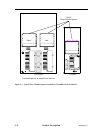

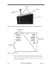
TLS-84xx or one side o
f
a 88xxx dual sided library
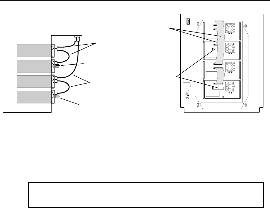
Drive 1
Drive 2
Drive 3
Drive 4
Terminator
Bridge Cables
Terminator
Bridge Cables
Terminators (2)
{
|
}
~
Bridge Cables (4)
{
|
Figure 4-2 TLS-54xx, 58xxx, 64xx, 68xxx, 84xx and 88xxx Drive Cabling Diagram
4.3 Installing a Fibre Channel Option
CAUTION
Be sure to turn the library’s power off before installing or removing a Fibre Chan-
nel Option.
4.3.1 Installation
The following steps outline the actions necessary to install a Fibre Channel Option
onto a library.
1. Remove power from the TLS: first turn the power switch off and then remove the
power cord.
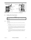
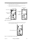
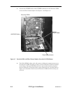
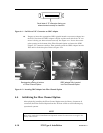
2. Using a Phillips screwdriver remove the six screws securing the service panel on
the rear of the library – refer to Figure 4-4. Depending of the model of library,
the service panel may not have ventilation slots. Care must be taken to not re-
move the four screws securing the heatsink panels. Save the service panel for
possible future use.
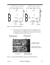
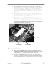
3. For TLS-4212 and 4222 libraries only, the aluminum bracket attached to the top
of the FCO must be removed before the FCO is installed. Use a Phillips screw-
driver to remove the two screws and the bracket from the top of the FCO. See
Figure 4-3.
501440 Rev. G FCO Type A Installation 4-3