


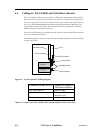
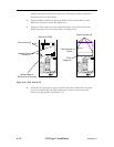
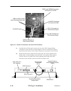
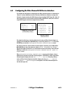
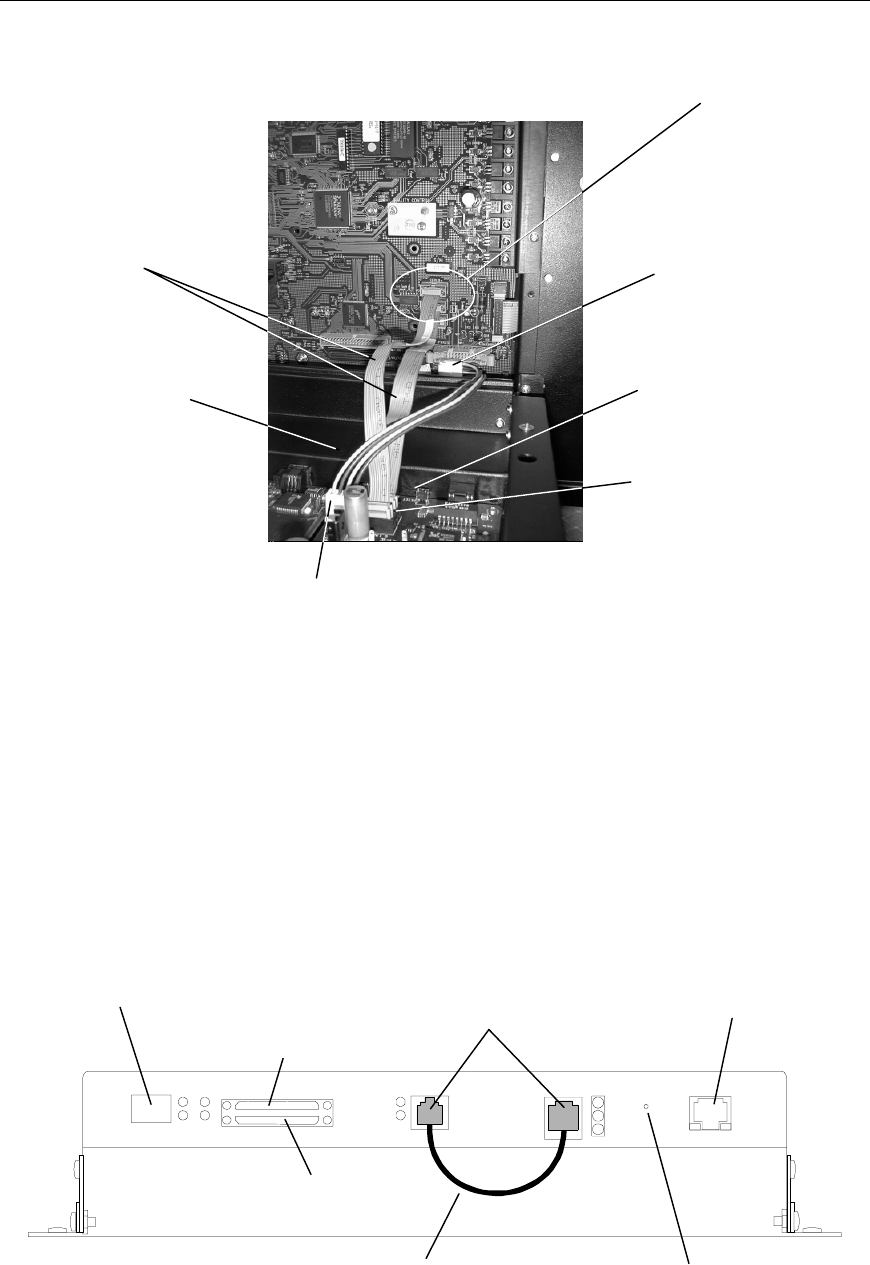
SERLA and SERLB Connectors
on Executive IV PCBA
FCO_A Connector on
Fibre Channel Option
SERIAL Ribbon Cables
Note: Red edge faces right.
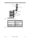
A
UXPWR Connector
on Executive PCBA
PWRIN Connector on
Fibre Channel Option
AUXPWR Cable
Q_LINK Connector on
Fibre Channel Option
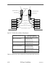
Figure 6-14 Detail of Connections (Executive IV PCBA Shown)
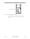
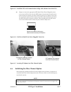
11. Carefully lift the FCO until it touches the rear of the TLS. Using a Phillips
screwdriver, secure the Fibre Channel Option to the rear of the TLS by tighten-
ing all four of the captive screws. Refer to Figure 6-10 for captive screw locations.
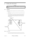
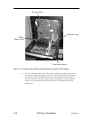
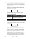
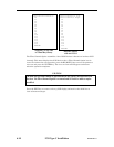
12. Install the FCO serial communication bridge cable. The serial communication
bridge cable is a short telephone type cable with a six-conductor RJ11 plug on
each end. Insert each ended of the serial communication bridge cable (P/N-
510149-01-6) into the RJ11 jacks on the FCO. See Figure 6-15.
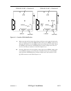
External Cable to
Host Ethernet Interface
(RJ45)
Reset Button
Serial Jumper
Connectors
(RJ11)
SCSI Channel 0
SCSI Channel 1
Fibre Channel 0
SFP Interface
Serial Communication
Bridge Cable
6-16 FCO Type C Installation 501440 Rev. G