


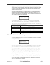
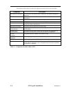
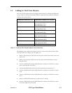

5.3 Cabling for TLS-412xxx Libraries
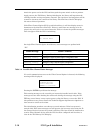
Note that all TLS-412xxx models are shipped from the factory without the SCSI inter-
connect cables or terminators installed. Table 5-2 represents the preferred cabling for
a library with 12 tape drives.
Connectors on Rear of FCO Connectors on Rear of TLS-412xxx
SCSI Channel 0 Left Medium Changer
Left Tape Drive 1 (LT1)
Left Tape Drive 2 (LT2)
SCSI Channel 1 Left Tape Drive 3 (LT3)
Left Tape Drive 4 (LT4)
SCSI Channel 2 Left Tape Drive 5 (LT5)
Left Tape Drive 6 (LT6)
SCSI Channel 3 Right Tape Drive 1 (RT1)
Right Tape Drive 2 (RT2)
SCSI Channel 4 Right Tape Drive 3 (RT3)
Right Tape Drive 4 (RT4)
SCSI Channel 5 Right Tape Drive 5 (RT5)
Right Tape Drive 6 (RT6)
Serial DB9 (Right Executive IV, SERL A)
Table 5-2 Preferred Fibre Channel Option Cable Connections
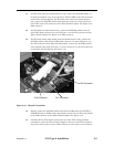
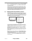
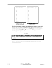
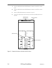
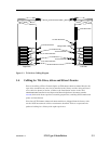
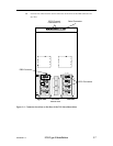
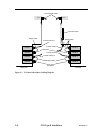
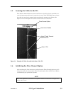
The following steps outline the actions necessary to connect the cables from the FCO
to the TLS. Please see Figure 5-2 and Figure 5-3.
1. Remove power from the TLS: first turn the power switch off and then remove the
power cord.
2. Remove power from the FCO: first turn the power switch off and then remove
the power cord.
3. Connect a SCSI Cable from the SCSI Channel 0 connector on the FCO to connec-
tor A on the left side on the TLS.
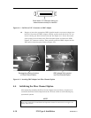
4. Connect the SCSI Bridge Cable (very short cable) from connector B to C.
5. Connect a SCSI Cable from the SCSI Channel 1 connector on the FCO to connec-
tor E.
6. Connect a SCSI Cable from the SCSI Channel 2 connector on the FCO to connec-
tor G.
7. Attach an LVD SCSI terminator at connectors D, F and H.
8. Connect a SCSI Cable from the SCSI Channel 3 connector on the FCO to connec-
tor I on the right side on the TLS.
501440 Rev. G FCO Type B Installation 5-3