


Quatech, Inc. AirborneDirect™ User Manual
18 2/21/2011 100-8510-110
6.0 Pin out and Connectors
Pin definition is dependent upon the device type selected. The following defines the pin
outs for the individual interfaces.
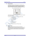
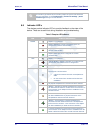
6.1 Serial Ports
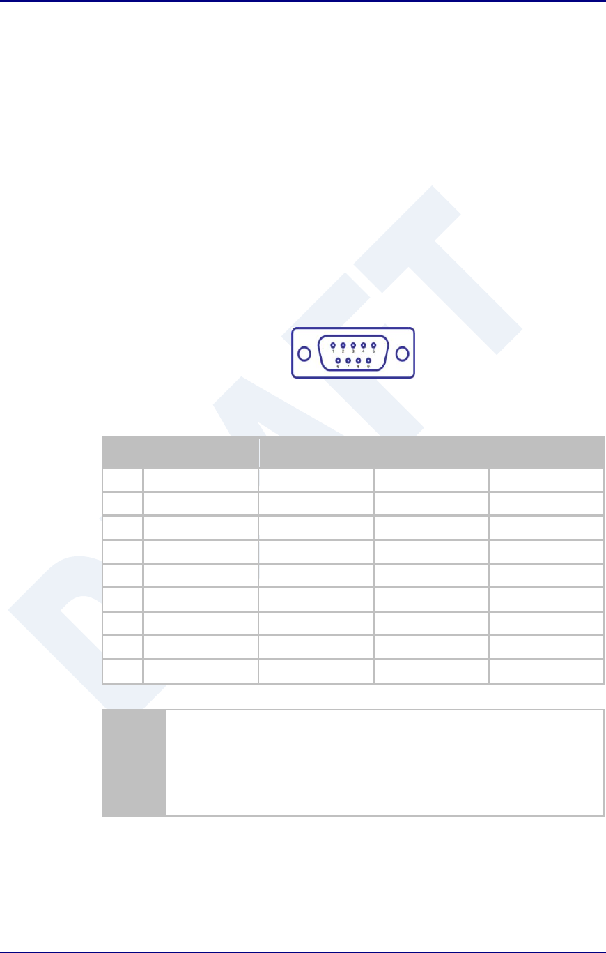
The AirborneDirect™ units support either a single or dual serial port
configuration. The Port pin out can change depending upon the interface
configuration chosen, Table 1 shows the pin out for the interface selected.
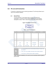
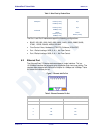
Figure 6 - DE-9 (DB-9) Connector Pin-out
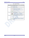
Table 1 – Serial Port Pin Definition
Pin
RS232 (DTE)
RS232 w/
Power on pin 9
2
RS422
RS485
1
No Connect
No Connect
No Connect
No Connect
2
RxD
RxD
RxD+
Connect to pin 3
3
3
TxD
TxD
TxD+
TxD+/RxD+
4
No Connect
No Connect
No Connect
No Connect
5
GND
GND
GND
GND
6
No Connect
No Connect
RxD-
Connect to pin 9
3
7
RTS
RTS
No Connect
No Connect
8
CTS
CTS
No Connect
No Connect
9
No Connect
5VDC (Input)
TxD-
TxD-/RxD-
1. For 2-wire operation, the user must externally connect pin 3 to pin 2 and
pin 6 to pin 9.
2. Power on pin 9 only available on Enterprise devices (ABDG-SE-DP501).
3. Only required on Industrial products (ABDG-SE-IN54XX)
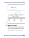
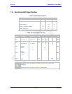
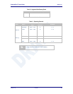
Table 2 shows the availability of the serial ports and available interface types by
product class.