


AirborneDirect™ Users Guide Quatech, Inc.
100-8510-110 2/21/2011 27
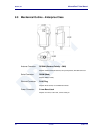
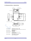
8.0 Antenna
The unit supports antenna connection through a single Hirose U.FL connector, located on
the top surface of the radio next to the RF shielding.
Any antenna used with the system must be designed for operation within the 2.4GHz
ISM band and specifically must support the 2.412GHz to 2.482GHz for 802.11b/g
operation. They are required to have a VSWR of 2:1 maximum referenced to a 50
system impedance.
8.1 Antenna Selection
The Airborne radio supports a number of antenna options, all of which require
connection to the U.FL connectors on the radio. Ultimately the antenna option
selected will be determined by a number of factors, including consideration of the
application, mechanical construction and desired performance. Since the number
of possible combinations is endless we will review some of the more common
solutions in this section. If your application is not covered during this discussion
please contact Technical Support for more specific answers.
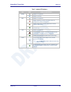
The available antenna connections include:
Host board mounted antenna
Host Chassis mounted antenna
Embedded antenna
In addition to the above options, location and performance need to be
considered. The following sections discuss these items.
8.2 Host Board Mounted Antenna
Host board mounted requires that an antenna connection is physically mounted
to the host system board. It also requires that the host board include a U.FL
connector (two (2) if diversity is being used) to allow a U.FL to U.FL coaxial lead
to connect from the radio to the host board. It will then require 50 matched PCB
traces to be routed from the U.FL connector to the antenna mount.
There are several sources for the U.FL to U.FL coaxial cable these include
Hirose, Sunridge and IPEX. Please contact Quatech for further part numbers and
supply assistance.
This approach can simplify assembly but does require that the host system
configuration can accommodate an antenna location that is determined by the
host PCB. There are also limitations on the ability to seal the enclosure when
using this approach.
This approach also restricts the selection of available antenna. When using this
approach, antennas that screw or press fit to the PCB mount connector must be
used. There are many options for the antenna connector type, however if you