Chapter 1 Introduction ASM-60 Installation and Operation Manual
1-4 Functional Description
1.3 Functional Description
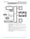
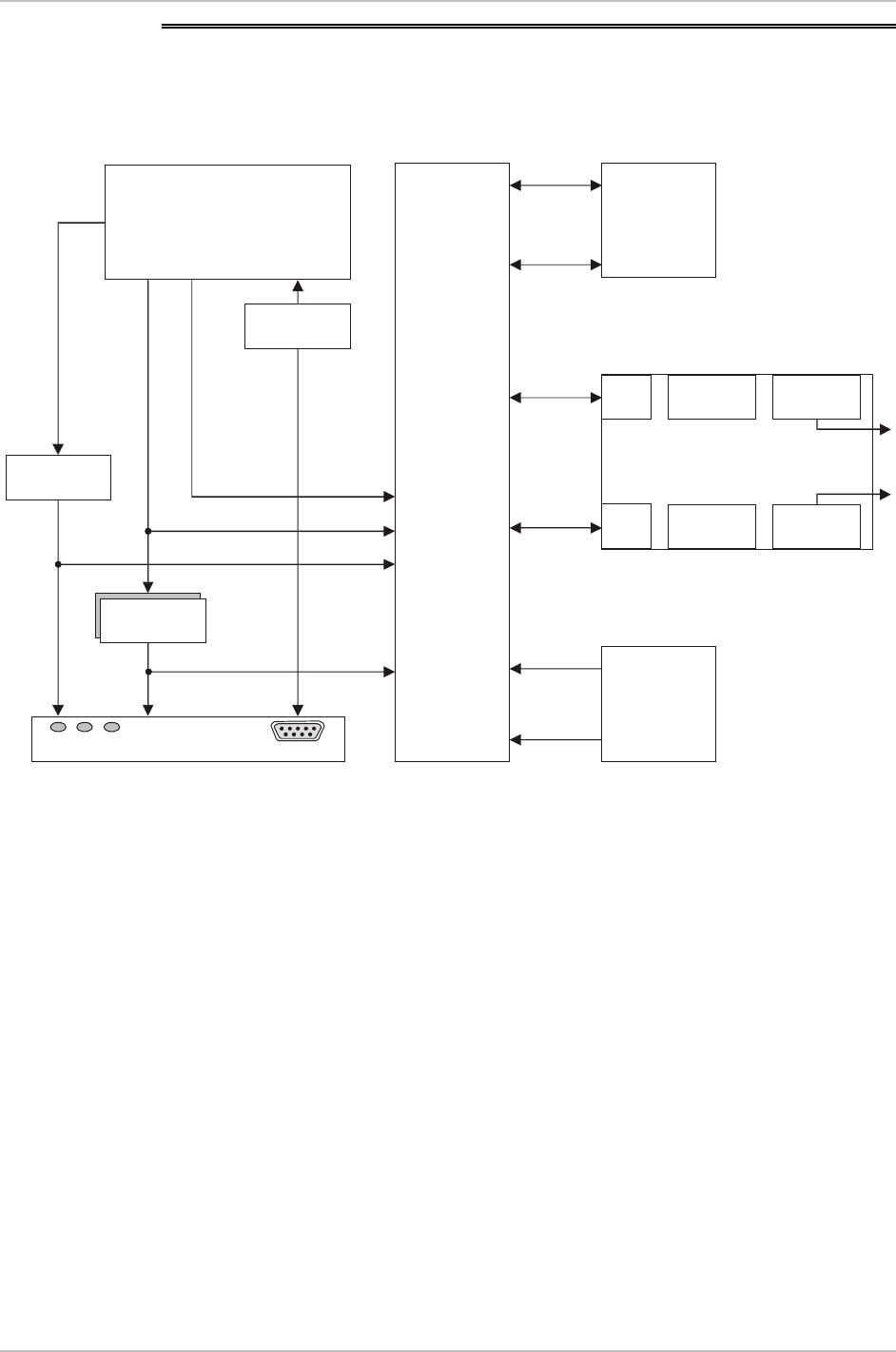
This section provides a functional description (Figure 1-3) of ASM-60 in the form of
block diagrams.
CPU
Additional
Decoder
Latch/Buffer
D8-D15
VDSL
Framer
DTE Interface
TxD, RxD
INT, EXT
Clock
Data,
Clock
Data,
Clock
3.3V
5.0V
AC
Power
Supply
A0-A7, A14
A11-A15
LEDs Control
RS-232
VDSL
Line Interface
EVM1 HYBRID1
HYBRID2 TRANSF.2
Line B
Line A
TRANSF.1
EVM2
Figure 1-3. ASM-60 Block Diagram
The ASM-60 modem consists of the following major modules:
• CPU and Peripherals – This module, based on a microprocessor, includes
Flash (1 Mb), RAM (0.5 Mb) and EEPROM (8 kb) memory and controls the
ASM-60 operation.
• VDSL Framer – This module encapsulates data bit stream coming from DTE
and transmits it over two different analog lines. At the other end, it reverses the
process by converting the two line data into one bit stream for the DTE. In
addition, the VDSL framer supplies clock to the DTE.
• VDSL Line Interface – Consists of two identical DSP modules. Each module
transmits and receives signals over 2-wire at half of the data rate that running
into the DTE interface.


