


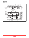
HD49335NP/HNP
Rev.1.0, Feb.12.2004, page 13 of 29
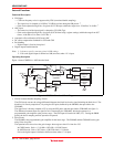
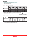
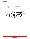
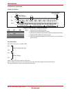
Dummy Clamp
It adjusts the mis-clamp which occurs when taking the photo under the highlight conditions. (Like a sun) Normally it
woks with the OB clamp, however when black level is out of the range caused by hightlight enter to OB part, it changes
to clamp processing by dummy bit level. Resister settings are follows.
D12, D11, D10 of address H'F7 (Dummy CP)
0, 0, 0 ; OFF
0, 0, 1 ; +32
0, 1, 0 ; +64
0, 1, 1 ; +96
:
:
1, 1, 1 ; +224
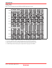
The amount of offset are changes automatically
depends on PGA gain in the LSI.
D8, D8 of address H'F7 (DMCG)
The amount of feed back current can be
reduced with only dummy clamp.
Data = 0:1/4
1:1/8
2:1/16
3:1/32
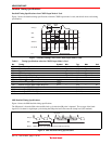
D10 to D12 of address H'F7
Note: OB/Dummy switching part has 1/8 hysteresis of threshold value.
D8 to D9 of address H'F7
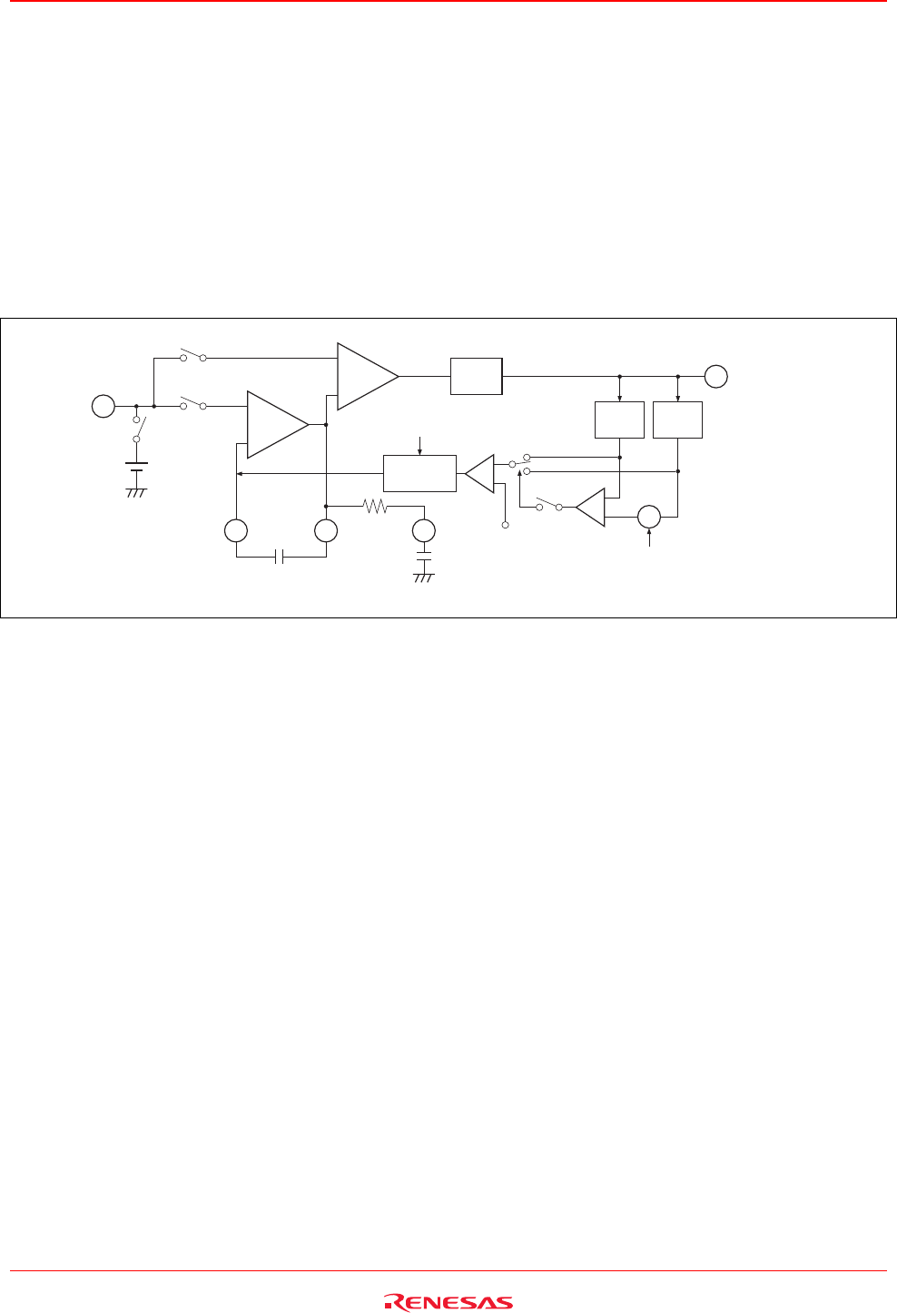
Digital output
CDS
AGC
CDS_in
BLKFB
BLKSH
SH
AMP
VRT
SP1
SP2
SP1
on/off
Clamp level
+
−
−
+
+
(+)
(−)
ADC
OB
DET
Current
cell
Dummy
DET
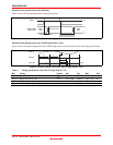
Detect 4clk
from OPDM edge
Detect 8clk
from OBP edge
Figure 7 Internal Bias Circuitry