HD49335NP/HNP
Rev.1.0, Feb.12.2004, page 7 of 29
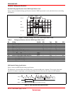
3. Automatic Offset Calibration Function and Black-Level Clamp Data Settings
The DAC DC voltage added to the output of the PGA amplifier is adjusted by automatic offset calibration.
The data, which cancels the output offset of the PGA amplifier and the input offset of the ADC, and the clamp data
(14 LSB to 76 LSB) set by register are added and input to the DAC.
The automatic offset calibration starts automatically after the RESET mode set by register is cancelled and
terminates after 40000 clock cycles (when fclk = 20 MHz, 2 ms).
4. DC Offset Compensation Feedback Function
Feedback is done to set the black signal level input during the OB period to the DC standard, and all offsets
(including the CCD offset and the CDSAMP offset) are compensated for.
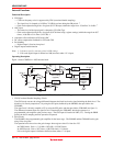
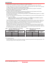
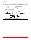
The offset from the ADC output is calculated during the OB period, and SHAMP feedback capacitor C3 is charged
by the current DAC (see figure 1).
The open-loop differential gain (∆Gain/∆H) per 1 H of the feedback loop is given by the following equation. 1H is
the one cycle of the OBP.
∆Gain/∆H = 0.078/(fclk × C3) (fclk: ADCLK frequency, C3: SHAMP external feedback capacitor)
Example: When fclk = 20 MHz and C3 = 1.0 µF, ∆Gain/∆H = 0.0039
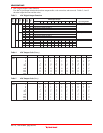
When the PGAMP gain setting is changed, the high-speed lead-in operation state is entered, and the feedback loop
gain is increased by a multiple of N. Loop gain multiplication factor N can be selected from 2 times, 4 times, 8
times, or 16 times by changing the register settings (see table 1). Note that the open-loop differential gain
(∆Gain/∆H) must be one or lower. If it is two or more, oscillation occurs.
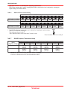
The time from the termination of high-speed lead-in operation to the return of normal loop gain operation can be
selected from 1 H, 2 H, 4 H, or 8 H. If the offset error is over 16 LSB, the high-speed lead-in operation continues,
and when the offset error is 16 LSB or less, the operation returns to the normal loop-gain operation after 1 H, 2 H, 4
H, or 8 H depending on the register settings. (Refer to table 2.)
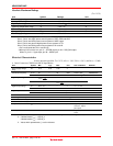
Table 1 Loop Gain Multiplication Factor during
High-Speed Lead-In Operation
Table 2 High-Speed Lead-In Operation
Cancellation Time
HGain-Nsel
(register settings)
Multiplication
Factor N
HGstop-Hsel
(register settings)
Cancellation
Time
[0]
L
H
L
H
[1]
L
H
H
L
4
32
16
8
[0]
L
H
L
H
[1]
L
H
H
L
1 H
8 H
4 H
2 H
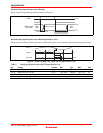
5. Pre-Blanking Function
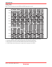
During the PBLK input period, the CSD input operation is separated and protected from the large input signal. The
ADC digital output is fixed to clamp data (14 to 76 LSB).


