


( 16 / 42 )
4.3 Description of Switches
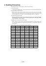
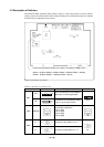
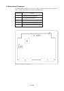
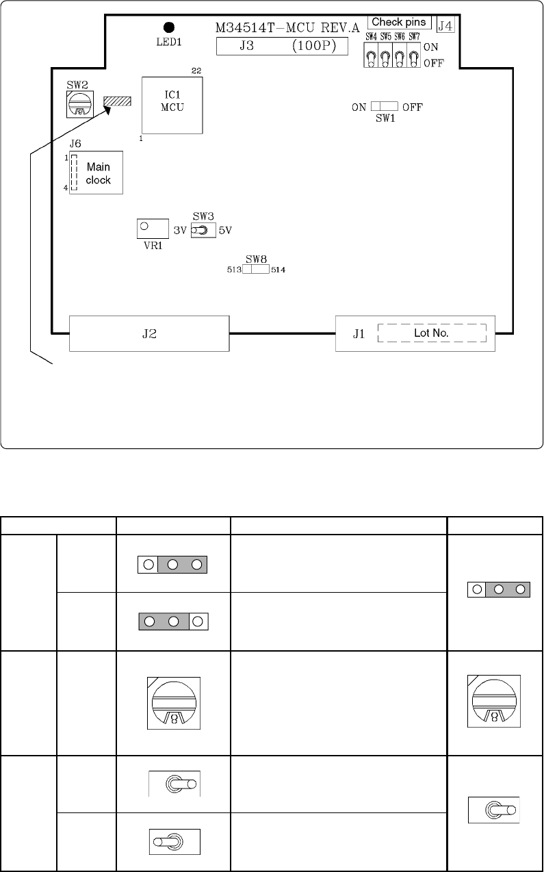
The M34514T-MCU board has eight switches. Figure 4.3 shows the positions of these switches.
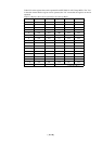
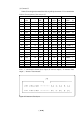
Tables 4.2 and 4.3 list the functions of the switches and the preset switch positions that are set before
the MCU board is shipped from the factory.
Figure 4.3 Positions of switches
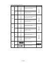
Table 4.2 Functions of switches (1/2)
For the products with the following lot numbers, the position of SW8 is here:
8FS001 - 8FS005, 8GS006 - 8GS020, 8KS021 - 8KS040, 9AS001 - 9AS020,
9CS021 - 9CS060, 9GS061 - 9GS090, 9JS091 - 9JS140
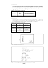
Connects the VDD of the M34514T-MCU
to the VDD of the target system.
Set the MCU’s ROM size.
• Set "2" (M2)
• Set "4" (M4)
• Set "6" (M6)
• Set "8" (M8)
Operates the target MCU at +5 V.
Operates the target MCU at + 3 V.
8
SW1
SW2
SW3
OFF
ON
5 V
3 V
OFF
5V
Label
Switch position
Description
Factory-setting
ROMSIZE
OFF
OFF
ON
ON
3V
3V
5V
5V
Does not connect the VDD of the M34514T-
MCU to the VDD of the target system.